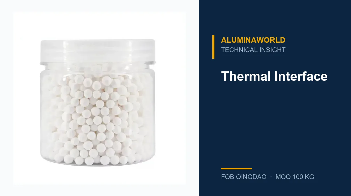
Alumina Powder for Thermal Interface Materials (TIM): Bimodal Packing to Reach 6 W/mK
Abstract. Thermal interface materials (TIMs) are the thermal bridge between an integrated circuit die and the heat sink, and the choice of filler powder determines the composite's thermal conductivity, coefficient of thermal expansion (CTE), and reliability under thermal cycling. This article covers how bimodal and tri-modal alumina particle packing is formulated to push composite conductivity to 5-7 W/mK (versus 2-3 W/mK for unimodal), how to select between epoxy, silicone and metal-alloy binders, how ASTM D5470 and JEDEC JESD22-A104 qualification tests are applied, and what failure modes (pump-out, delamination, migration) dictate material selection. Ten engineering FAQs cover interfacial thermal resistance, void fraction, cost per kg, and procurement specifications. For the related sintered alumina powder used in HTCC substrates, see our calcined alumina for lithium battery separator coatings, and for high-purity alumina in CMP slurries, see our high-purity alumina for semiconductor CMP slurry.
1. Why TIM thermal conductivity is a filler-loading problem
The thermal conductivity of a TIM composite is dominated by its filler volume fraction. The polymer matrix — epoxy or silicone — has a thermal conductivity of only 0.2-0.3 W/mK, while sintered alpha-alumina (99.5%+) has a thermal conductivity of 20-30 W/mK, two orders of magnitude higher. For a typical power module or CPU TIM, the thermal resistance budget allows only 0.05-0.15 °C·cm^2/W across a TIM layer 50-200 microns thick. That budget translates to a minimum composite conductivity of 3-6 W/mK, which in turn requires a filler volume fraction above 60%.
The constraint is rheology. As solid loading increases, the paste viscosity grows non-linearly, eventually becoming unworkable for screen printing, stencil printing, or syringe dispensing. Unimodal spherical packing caps out at about 60% filler by volume before the paste becomes a thick putty. Above that, the binder cannot wet the particles and the paste cracks during cure. Bimodal packing is the established workaround: a coarse population (20-50 micron) forms the load-bearing skeleton, and a fine population (1-5 micron) fills the interstitial voids, letting the composite reach 65-72% filler volume at a viscosity that remains screen-printable.
2. Packing density theory and the bimodal ratio
For spheres of identical size, the theoretical maximum packing density is 64% for random-close packing (RCP) and 74% for face-centered cubic (FCC) packing. Real polymer-filled composites with monodisperse filler rarely exceed 55-60% in practice. Bimodal packing was formalized by Furnas (1952): a coarse sphere array leaves interstitial voids whose size scales with the coarse sphere diameter, and a fine sphere with diameter D_small < D_large / 5 fits inside those voids without disturbing the coarse array. Cerezo and Maffei (1998) showed that for ideal bimodal packing with a 10:1 size ratio, the maximum packing density reaches 85%.
| Filler vol. % | Unimodal k (W/mK) | Bimodal k (W/mK) | Tri-modal k (W/mK) | Paste viscosity @25°C (Pa·s) |
|---|---|---|---|---|
| 40% | 1.1-1.5 | 1.4-1.8 | 1.6-2.0 | 500-1,500 |
| 50% | 1.8-2.4 | 2.5-3.2 | 2.8-3.5 | 2,000-8,000 |
| 55% | 2.3-3.0 | 3.4-4.3 | 3.8-4.6 | 8,000-30,000 |
| 60% | 2.8-3.6 | 4.2-5.3 | 4.7-5.8 | 25,000-100,000 |
| 65% | 3.4-4.3 | 5.0-6.2 | 5.6-6.8 | 100,000-300,000 |
| 70% | 4.0-5.0 | 5.8-7.0 | 6.5-7.5 | >500,000 (paste unusable) |
| 72%+ (tri-modal) | — | — | 7.0-8.5 (pre-cured pad) | Pre-cured only |
The practical industry sweet spot is a 6:1 to 15:1 size ratio with a coarse:fine weight ratio of 70:30 to 80:20. Typical bimodal TIM formulations use 20-50 micron spherical calcined alumina for the coarse mode and 1-5 micron reactive or calcined alumina for the fine mode. Tri-modal distributions (adding a 10-15 micron intermediate mode) can push packing above 88%, reaching composite conductivities of 7-8 W/mK in pre-cured gap-fills, but at significantly higher process complexity.
3. Alumina grades used as TIM fillers
Not all alumina powders are equal for TIM service. The selection depends on purity, particle morphology, size distribution, surface treatment, and bulk density. Below are the common grades used as TIM fillers, with the key differences:
| Filler type | Thermal conductivity (W/mK) | CTE (ppm/K) | Bulk density (g/cm3) | Typical size (micron) | Cost (USD/kg FOB) |
|---|---|---|---|---|---|
| Spherical calcined alumina (99.5%) | 20-30 | 7-9 | 2.4-2.7 | 20-50 | 4-12 |
| Submicron reactive alumina (5N, 99.999%) | 25-35 | 6-8 | 2.4-2.6 | 0.5-3 | 15-35 |
| Angular sintered alumina (99.7%) | 22-28 | 7-9 | 3.4-3.6 | 10-80 | 6-15 |
| Tabular alumina (T60/T64) | 25-35 | 6-7 | 3.6-3.7 | 20-150 | 8-20 |
| Hexagonal boron nitride (platelet) | 80-150 (in-plane) | 3-14 | 2.1-2.4 | 5-50 | 60-200 |
| Aluminum nitride | 100-180 | 4-5 | 3.1-3.3 | 1-20 | 100-400 |
| Epoxy matrix (unfilled) | 0.2-0.3 | 50-80 | 1.1-1.2 | — | 2-5 |
| Silicone matrix (unfilled) | 0.15-0.25 | 300-600 | 0.95-1.05 | — | 3-8 |
For most electronics TIM applications (automotive ECUs, LED drivers, power modules, server CPUs), spherical calcined alumina (99.5%, 20-50 micron, BET <1 m^2/g) is the workhorse coarse-mode filler, and submicron reactive alumina (5N, 0.5-3 micron) is the fine-mode filler. See our alumina powder product page for full specifications and order forms.
4. Binder selection: epoxy, silicone, and metal alloys
The polymer or metal binder is the second-most-important variable in TIM formulation. Three systems dominate the market:
4.1 Epoxy (permanent bond, high mechanical strength)
Epoxy is the default binder for TIMs that must survive thermal cycling and mechanical shock without pump-out — automotive ECU modules, power modules (IGBT, SiC), and LED drivers. A well-filled epoxy TIM reaches 4-6 W/mK conductivity and 15-25 MPa tensile strength (ASTM D638). Cure is typically at 120-150 degC over 15-30 minutes, compatible with most component-attach lines. CTE of 12-25 ppm/K when filled to 65%+ alumina volume, matching FR-4 PCB reasonably well.
4.2 Silicone (compliant, reworkable)
Silicone TIMs are used where the package must be disassembled or where pump-out resistance is critical. Lower Tg (-50 to -30 degC) keeps the paste compliant from -40 to +150 degC. Thermal conductivity typically 2-4 W/mK, lower than well-filled epoxy because of silicone's intrinsically low thermal conductivity (0.15-0.25 W/mK). Excellent creep relaxation reduces stress at the TIM-substrate interface under thermal cycling.
4.3 Metal alloys (highest conductivity, electrically conductive)
Indium-gallium eutectic (25:75, melting point 15.8 degC) and indium-tin pastes (85:15 In-Sn, 179 degC) are used in high-power LED stacks, laser diodes, and power transistor heat spreaders where peak conductivity above 8 W/mK is mandatory. These TIMs are electrically conductive and require careful isolation design. Indium-gallium is self-healing under thermal cycling — voids that form during cycling re-seal as the metal reflows — giving exceptional long-term reliability for stationary installations.
5. Thermal conductivity and reliability testing standards
TIM qualification follows a defined test matrix. The key standards and what they measure:
| Test standard | What it measures | Equipment | Specimen | Industry tolerance |
|---|---|---|---|---|
| ASTM D5470 | Thermal conductivity (W/mK) | Heat flow meter | 0.1-10 mm thick disk | ±3% |
| ASTM E1461 | Thermal diffusivity (mm2/s) | Laser flash analyzer (LFA) | 10-13 mm dia, 1-5 mm thick | ±5% |
| JEDEC JESD22-A104 | Temperature cycling reliability (-55 to +125°C) | Thermal chamber + DUT | 1000 cycles | <10% Rth increase |
| JEDEC JESD51-18 | Theta_JC / Theta_JB thermal resistance | Transient hot-resistance test | Packaged DUT | ±5% |
| ASTM D4236 | Void content (%) | Micro-CT / optical microscopy | 5x5x5 mm cube | <5% cross-section |
| ISO 9079 | Viscosity (Pa·s) at 25°C | Rotational rheometer | 10 mL sample | ±10% |
| ASTM D4951 | CTE (ppm/K) | Dilatometer (TMA) | 10x3x3 mm | ±1 ppm/K |
A typical qualification protocol for an automotive ECU TIM: (1) ASTM D5470 baseline thermal conductivity at +25 degC and +125 degC, (2) ASTM D4951 CTE measurement, (3) JEDEC JESD22-A104 temperature cycling (-40 to +125 degC, 1000 cycles), (4) JEDEC JESD51-18 Theta_JC extraction, and (5) ASTM D4236 void content on cured cross-section. Acceptance criteria are typically <10% thermal resistance increase after cycling and <5% void area on cross-section.
6. CTE matching, void control, and interfacial resistance
Three physical parameters beyond raw conductivity dictate TIM reliability: CTE mismatch, void fraction, and interfacial thermal resistance.
6.1 CTE matching
CPU silicon has a CTE of about 2.6 ppm/K, FR-4 PCB 14-18 ppm/K, and unfilled epoxy TIM 50-80 ppm/K. The CTE step at the TIM-substrate interface is the root cause of delamination under thermal cycling. Adding high-fill alumina (CTE 7 ppm/K) brings the composite CTE to 12-25 ppm/K, reducing the mismatch to 1-7 ppm/K versus FR-4. For a 0.5 mm TIM under 120 K thermal cycling, the strain reduction is 3-5x versus unfilled epoxy.
6.2 Void control
Void fraction in the cured TIM is a thermal resistance killer because air has a thermal conductivity of only 0.026 W/mK. At 10% void volume, composite conductivity drops by 8-12%; at 20% it drops by 18-25%. Industry acceptance is <5% void area on cured cross-section (ASTM D4236). Void formation is controlled by: (1) vacuum degassing the mixed paste at 0.2 bar for 15 minutes, (2) controlled cure ramp at 2-3 degC/min to 150 degC (allows trapped volatiles to escape), (3) screen or stencil printing application rather than syringe (mechanical rolling minimizes bubble entrapment), and (4) substrate surface preparation — plasma or corona treatment before TIM application reduces adhesion-driven void nucleation.
6.3 Interfacial thermal resistance
Even at high filler loading, phonon scattering at the solid-solid interface between alumina and polymer reduces effective conductivity. Surface treatments on the alumina filler reduce interfacial resistance (R_inter) by 30-70%: silane coupling agents (KH-570 for epoxy, KH-560 for silicone) form covalent Si-O-Al bonds; stearic acid or vinyl-triethoxysilane coatings on reactive alumina reduce R_inter to 1-2e-7 m^2-K/W from the untreated 2-5e-7 range. Hexagonal boron nitride or carbon nanotube interlayers at <1 wt% add 5-15% composite conductivity.
7. Five documented TIM failure modes
7.1 Pump-out
Cyclic thermal expansion squeezes the TIM paste out of the package joint, leaving voids that increase thermal resistance 30-80% over 500-1000 cycles. Prevention: use a compliant silicone or phase-change TIM rather than rigid epoxy, or use a high-fill alumina to reduce the CTE expansion differential.
7.2 Delamination
TIM-substrate bond fails under peel or shear stress from thermal cycling, mechanical shock, or CTE mismatch. Prevention: plasma or corona surface treatment of substrates before TIM application; silane-primed alumina fillers for covalent bonding across the interface.
7.3 Oxidation
Exposed TIM at temperatures above 150 degC oxidizes the polymer binder, increasing modulus and reducing compliance over time. Prevention: select high-Tg (>150 degC) epoxy systems for automotive and aerospace applications.
7.4 Migration
In metal-based TIMs (indium, silver), metal ions can migrate under DC bias voltage and cause short circuits in nearby traces. Prevention: thin PTFE or Kapton barrier between the TIM and active circuitry.
7.5 Moisture absorption
Unfilled epoxies absorb 0.5-2% moisture by weight, causing outgassing and blistering during cure. Prevention: dry-fillers before use, desiccant storage, or select inherently low-moisture-absorption matrix systems.
8. Procurement specification for TIM-grade alumina
When sourcing alumina for TIM formulations, the minimum specification package should cover:
- Chemistry: sintered alpha-alumina (99.5% Al2O3 minimum) for the coarse mode; reactive gamma-alumina (99.99%+, BET 50-150 m^2/g) for the fine mode.
- Morphology: spherical for paste TIMs; angular or platelet for pre-cured gap pads.
- Size: coarse mode 20-50 micron (D50 30-35 micron), fine mode 1-5 micron (D50 2-3 micron). Particle size distribution by laser diffraction (ISO 9276).
- Surface treatment: silane-coated (KH-570 for epoxy, KH-560 for silicone) or stearic acid coated on reactive alumina.
- Purity: Fe <200 ppm, Na <50 ppm, K <10 ppm (ICP-MS). For SiC/GaN modules, trace transition metals below 10 ppm.
- Bulk density: 2.4-2.7 g/cm3 for calcined; 0.5-1.5 g/cm3 for reactive (low density is inherent to high surface area).
- Moisture: loss on ignition <0.15% at 105 degC; pre-dried at 200 degC for 2 hours recommended.
- Packaging: 25 kg multi-wall paper bags with inner PE liner; vacuum-sealed or desiccant-filled for reactive alumina.
9. Cost per Watt of thermal conductivity
For a TIM formulation targeting 5 W/mK conductivity with a bimodal alumina fill, the raw material cost is approximately USD 8-15 per kg of cured composite, dominated by the epoxy resin system (USD 10-25/kg for high-Tg industrial grade) and the alumina powder (USD 4-12/kg for calcined coarse, USD 15-35/kg for reactive fine). A typical automotive ECU TIM usage is 1-5 grams per package, so the alumina cost per package is USD 0.003-0.015 — negligible versus the assembly cost. Boron nitride or aluminum nitride additives add USD 0.10-0.50 per package and are justified only when the conductivity target exceeds 6-7 W/mK.
10. Next steps
If you are evaluating TIM-grade alumina powders for your electronics cooling application, contact AluminaWorld for a technical data sheet (TDS), sample kit (100g reactive + 100g calcined), and compatibility testing protocol.
For related technical content, see our reactive alumina for epoxy potting thermal conductivity, ATH vs boron nitride for thermal management, and our alumina powder product page.
Engineering FAQ (10 Questions)
1. Why do TIM fillers need to be packed in a bimodal distribution instead of a unimodal one?
Unimodal packing of solid spheres has a theoretical maximum volume fraction of about 64% for random-close packing and 74% for face-centered cubic (crystalline) packing. Real-world epoxy-filled TIMs using a single particle size rarely exceed 55-60% filler by volume because the slurry viscosity explodes above that threshold. Bimodal packing uses a coarse population to form the load-bearing skeleton and a fine population to fill the interstitial voids between coarse particles. Theoretically, if the fine-to-coarse diameter ratio is 1:6, the maximum packing density reaches 83%; at a ratio of 1:10 it reaches 85-87%. Practically, a bimodal alumina-filled epoxy reaches 65-72% solid loading with workable viscosity, producing thermal conductivity of 4-6 W/mK versus 2-3 W/mK for unimodal. The key physics: the fine particles occupy the void space that the coarse particles cannot, so total solid fraction grows without proportionally growing viscosity.
2. What particle size ratio gives the best bimodal packing for TIMs?
The theoretical optimum for ideal bimodal spheres is a size ratio d_large/d_small of 10:1, predicted by the Furnas model (1952) and validated by Cerezo and Maffei (1998). In practice, TIM manufacturers use a 6:1 to 15:1 ratio because extreme ratios make the fine fraction too difficult to disperse and increase viscosity beyond practical limits. Typical industry bimodal formulations use 20-50 micron coarse alumina and 1-5 micron fine alumina, with a coarse:fine weight ratio of about 70:30 to 80:20. Tri-modal distributions (coarse + medium + fine) can push packing density above 88% but introduce three-times more rheological complexity and are generally reserved for high-performance gap-fills rather than paste-type TIMs.
3. What is the maximum achievable thermal conductivity with alumina-filled TIMs?
Pure alpha-alumina (99.95%+) has a thermal conductivity of about 30 W/mK. Using effective medium theory (Bergman-Pfaff, Maxwell-Eucken, and Lewis-Nielsen models), the maximum composite conductivity approaches 25 W/mK only if the filler volume fraction is above 75% and interfacial thermal resistance is negligible. Practically, commercial alumina-filled TIMs reach 5-7 W/mK for paste/pad products and 8-12 W/mK for pre-cured gap-fills, because the polymer matrix (epoxy or silicone) has a thermal conductivity of only 0.2-0.4 W/mK. To push beyond 7 W/mK with alumina alone, manufacturers switch to tri-modal packing, surface-coated alumina (silane-treated to reduce interfacial resistance), or blend with boron nitride or aluminum nitride (10-150 W/mK) as a secondary filler. For applications above 10 W/mK, silver, aluminum, or indium-gallium eutectic metal-based TIMs become competitive.
4. What binder matrix is used — epoxy, silicone, or something else?
Three matrix systems dominate: (1) Epoxy — most common for permanent TIM bonds in power electronics, automotive ECUs, and LED drivers. Offers excellent mechanical strength (15-25 MPa tensile, ASTM D638), low creep, and CTE 40-80 ppm/K when well-filled. Cures at 120-150 degC over 15-30 minutes, which is compatible with most component-attach lines. Thermal conductivity typically 3-6 W/mK. (2) Silicone — used where pump-out resistance and compliance under thermal cycling are critical, e.g. BGA underfill and mobile device heat spreaders. Lower Tg (-50 to -30 degC), so the paste stays compliant down to -40 degC. Thermal conductivity 2-4 W/mK. Excellent creep relaxation but poorer adhesion. (3) Metal alloys — indium-gallium (25:75 eutectic, melting point 15.8 degC) and indium-based pastes (85:15 In-Sn at 179 degC) for high-power LED and laser diode stacks. Conductivity 8-13 W/mK and self-healing under thermal cycling, but conductive so require careful electrical isolation design. Selection rule: if the TIM does not conduct electricity and the bond is permanent, epoxy. If electrical isolation is needed but rework matters, silicone. If peak conductivity above 8 W/mK is non-negotiable, metal alloy.
5. How is TIM thermal conductivity measured and what standard is used?
ASTM D5470 is the primary test method for thermal conductivity of electrical insulation, including TIMs. It uses a heat flow meter (HF-11, HF-12, or LFA-467 variant) with guard heaters to eliminate edge losses. Test specimen is a 25-100 mm diameter disk or pad, 0.1-10 mm thick, sandwiched between a hot plate and a cold plate at a controlled delta-T of 10-20 K. Steady-state is reached in 5-15 minutes and thermal conductivity is calculated from heat flux and temperature gradient across the sample thickness. For anisotropic TIMs (e.g., graphite composites or film-gap-pads), ASTM D5930 measures directional conductivity. For thin-film TIMs below 0.1 mm, laser flash analysis (ASTM E1461, LaserFlash 467) is more appropriate, measuring thermal diffusivity alpha, then multiplying by volumetric heat capacity rho*Cp to get k = alpha * rho * Cp. JEDEC JESD51-18 specifies the thermal resistance Theta_JC (junction-to-case) and Theta_JB (junction-to-board) extraction from the transient hot-resistance method (Cauer or Foster network fitting).
6. What is interfacial thermal resistance and how do you reduce it?
Interfacial thermal resistance (R_inter = 1/h, units cm^2-K/W) is the thermal resistance that appears at the boundary between the filler particle and the polymer matrix, caused by phonon scattering at the solid-solid interface. Even if the filler itself has 30 W/mK conductivity, a poorly-bonded interface with h = 5 MW/m^2-K adds 2e-7 m^2-K/W of resistance, which is comparable to the bulk polymer resistance for a 0.5 mm thick TIM. Typical R_inter for untreated alumina-epoxy is 2e-7 to 5e-7 m^2-K/W. Surface treatments reduce it by 30-70%: silane coupling agents (KH-570 for epoxy, KH-560 for silicone) form covalent Si-O-Al bonds that bridge the filler-matrix phonon mismatch. Graphene oxide, hexagonal boron nitride, or carbon nanotube interlayers between alumina particles act as phonon bridges, adding 5-15% conductivity at <1 wt% additive. The most effective treatment for reactive alumina is a stearic acid or vinyl-triethoxysilane coating, which reduces R_inter to 1-2e-7 m^2-K/W and is compatible with both epoxy and silicone matrices.
7. What particle morphology — spherical, angular, platelet, or irregular — is best for TIMs?
Spherical alumina is preferred for paste TIMs because it minimizes viscosity for a given solid loading and provides uniform thermal conduction paths in all three dimensions. Angular or irregular particles pack more densely in some formulations but increase viscosity 2-3x at the same loading and create stress concentrators under thermal cycling. Platelet-shaped alumina (calcined tabular alumina ground into platelets) is used in film-type gap pads and prepreg substrates where high through-plane CTE and in-plane dimensional stability matter. For TIM pastes targeting 5-7 W/mK, the industry standard is spherical calcined alumina 20-50 micron for the coarse mode and sub-5 micron spherical reactive or calcined alumina for the fine mode. Tabular alumina is reserved for ceramic substrates (HTCC/DBC) where dimensional tolerance under 1500-1600 degC sintering matters.
8. What is CTE matching and why does it matter?
The coefficient of thermal expansion (CTE) mismatch between the TIM and the bonded substrates is the root cause of delamination under thermal cycling. CPU substrate CTE is about 6-15 ppm/K (Si), printed circuit board CTE is 14-18 ppm/K (FR-4), and TIM CTE is 30-120 ppm/K for unfilled epoxy. Under a +80 to -40 degC thermal cycle (120 K delta), a 0.5 mm thick TIM with 80 ppm/K CTE expands or contracts about 0.6 microns per cycle, producing cumulative shear strain at the TIM-substrate interface. After 1000 cycles at 10C/min, unmodified epoxy TIMs show 30-50% conductivity drop. Adding high-fill alumina (CTE 7 ppm/K) brings the composite TIM CTE to 12-25 ppm/K, reducing the CTE mismatch to 1-7 ppm/K vs FR-4. JEDEC JESD22-A104 (temperature cycling -55 to +125 degC, 1000 cycles) is the standard qualification test. After qualification, the TIM must show <10% thermal resistance degradation versus initial Theta_JC.
9. How does TIM void fraction affect performance?
Voids in a cured TIM act as thermal insulators because air has a thermal conductivity of 0.026 W/mK, two orders of magnitude lower than the filled composite. At 5% void volume, TIM conductivity drops by 3-5%; at 10% it drops by 8-12%; at 20% it drops by 18-25%. Void fraction is measured by ASTM D4236 on cured TIM cross-sections using optical microscopy or micro-CT scanning (voxel resolution 5-10 microns). Standard industry acceptability criteria for TIM paste bonds are <5% void area on 100x optical cross-sections; <3% for high-power LED and laser diode applications. Void formation is controlled by: (1) vacuum degassing of the mixed paste (15 min at 0.2 bar), (2) controlled cure ramp (not too fast — 2-3 degC/min up to 150 degC to allow trapped volatiles to escape), (3) application method — screen printing and stencil printing produce the lowest void content because the paste is mechanically rolled out, versus syringe application which can trap bubbles under high-viscosity conditions.
10. What are common TIM failure modes and how do you prevent them?
Five documented failure modes in TIMs: (1) Pump-out — cyclic thermal expansion/contraction progressively squeezes the TIM paste out of the package joint, leaving voids that increase thermal resistance 30-80% over 500-1000 cycles. Prevention: use a compliant silicone or phase-change TIM (melting point 30-60 degC) rather than a rigid epoxy, or use a higher CTE filler to reduce the expansion differential. (2) Delamination — TIM-substrate bond fails under peel or shear stress from thermal cycling, mechanical shock, or CTE mismatch. Prevention: plasma or corona surface treatment of substrates before TIM application; silane-primed alumina fillers. (3) Oxidation — exposed TIM at high temperatures (>150 degC) oxidizes the polymer binder, crosslinking it to higher modulus and lower compliance. Prevention: select high-Tg (>150 degC) epoxy systems for automotive and aerospace applications. (4) Migration — in metal-based TIMs (indium, silver), metal ions can migrate under DC bias voltage, causing short circuits in nearby traces. Prevention: use a thin PTFE or Kapton barrier between the TIM and active circuitry. (5) Moisture absorption — unfilled epoxies absorb 0.5-2% moisture by weight, causing outgassing during cure (blistering, voids). Prevention: dry-fillers before use, desiccant storage, or select inherently low-moisture-absorption matrix systems.
11. What is a 'phase-change' TIM and when should I use it?
Phase-change TIMs are solid at room temperature but transition to a semi-liquid state at a controlled temperature (typically 40-80 degC), allowing them to flow into microscopic surface asperities under the junction heat load. They combine the handling convenience of a solid pad (no mess, no mixing) with the conformity of a paste. Thermal conductivity of commercial phase-change TIMs (e.g., Honeywell PTM7300 / PTM7500, Henkel MasterBond, 3M TC600) is 5-13 W/mK after in-situ flow. Best suited for flip-chip and high-density BGA packages where surface roughness is high (Ra > 3 microns) and where a rigid epoxy would leave 30-50% air gaps. Not recommended for applications above 100 degC long-term, where the phase-change polymer degrades.
12. How much does TIM-grade alumina powder cost per kg?
TIM-grade spherical calcined alumina (99.5%+, 20-50 micron, BET <1 m^2/g) costs USD 4-12/kg FOB China at 25 MT annual volume. High-purity reactive alumina (5N, sub-5 micron fine-mode filler) costs USD 15-35/kg. Compared to boron nitride (USD 60-200/kg for platelet BN 99%+) and aluminum nitride (USD 100-400/kg), alumina is the most cost-effective high-conductivity filler and is used in 70-80% of commercial TIM formulations. The price ratio makes alumina the base filler in nearly every high-volume application (automotive LED, ECU, power module, server CPU/GPU TIMs). Aluminum nitride is added as a secondary filler only when the target conductivity exceeds 8 W/mK and the cost premium is absorbed by the end-product margin.
Contact
For technical consultation, samples, or a quote on TIM-grade alumina powders:
- WhatsApp: +86 133 2522 2240
- Email: barry@aluminaworld.com
- Web: okkinc.com