Molecular Sieve 3A for Jet Fuel (Jet A-1 / JP-8) Drying: Why 3 Angstrom Pore Beats 13X, 4A, and Silica Gel
Every kilogram of jet fuel leaving a refinery holds 30 to 75 ppm of dissolved water; a Boeing 737 burns 2,500 to 3,000 kg of fuel per hour, and at altitude the fuel cools to -40 C — a temperature at which the dissolved water comes out of solution as ice crystals that can block fuel lines, starve an engine, and trigger an in-flight flameout. This guide covers the 3 Angstrom pore window that admits water but rejects the entire hydrocarbon matrix, the ASTM D1655 and MIL-DTL-83133 specification chain, the ELIMINATE test for Fuel System Icing Inhibitor compatibility, why hydroprocessed sustainable aviation fuels (HEFA, F-T, ATJ) are more demanding for molecular sieve drying than conventional Jet A-1, the regeneration temperature and energy profile, the seven mandatory quality-control tests for AW-3A-AVI procurement, and a 10-year field service-life case study from major fixed-base operators.
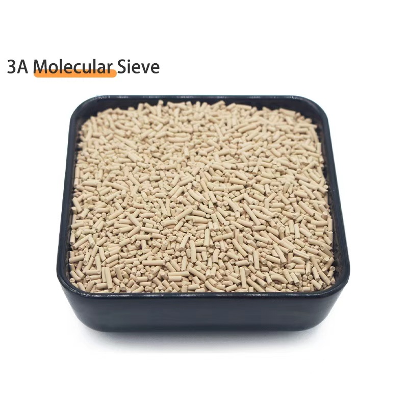
Why Jet Fuel Drying Is Different from Every Other Molecular Sieve Application
Aviation turbine fuel (Jet A, Jet A-1, JP-5, JP-8) is the only industrial hydrocarbon that operates in a temperature envelope of -55 C (ground hold at high-altitude airfield in winter) to +55 C (desert ramp), with a sustained operating temperature of -40 C at FL350 cruise. No other molecular sieve application has that temperature range. The fuel itself is a mixture of 350 to 500 hydrocarbon species with boiling range 150 to 300 C, and the dissolved water content is tightly bound to the aromatics and naphthenes by hydrogen bonding. At -40 C, the water saturation point of Jet A-1 drops below 30 ppm; above 100 ppm, free water drops out of solution as ice crystals. The fuel tank of a commercial transport aircraft holds 50,000 to 150,000 L of fuel, and a single ice crystal event in the fuel feed line to the boost pump can take an engine offline.
The defense against ice formation is twofold: (1) Fuel System Icing Inhibitor (FSII), typically diethylene glycol monomethyl ether (DiEGME) added at 0.10 to 0.15 vol% in JP-8 (mandatory under MIL-DTL-83133) or as an option in Jet A-1 under ASTM D1655, which keeps the water in solution at sub-zero temperatures; (2) molecular sieve drying of the fuel at the ground fueling filter-separator to keep the inlet water below 30 ppm and remove the dissolved water that the FSII cannot handle. The two are complementary — FSII handles the residual water that survives the molecular sieve, and the molecular sieve removes the bulk water that would overwhelm the FSII capacity.
The molecular sieve choice is uniquely constrained by the requirement to exclude the entire hydrocarbon matrix of the fuel while admitting water. The pore size of 3 Angstrom is the only commercial pore window tight enough to admit water (2.6 A kinetic diameter) and exclude the smallest n-paraffin (n-butane at 4.3 A kinetic diameter) — and through extension, all the larger paraffins, naphthenes, and aromatics in jet fuel. 4A molecular sieve (4 Angstrom pore) would co-adsorb n-pentane (4.3 A borderline) and n-hexane (4.9 A), reducing fuel LHV and saturating the bed within hours. 13X molecular sieve (9 A pore) would co-adsorb the entire boiling range and saturate within minutes. Silica gel has a non-uniform pore structure (1 to 30 nm distribution) that admits both water and a significant fraction of the hydrocarbon matrix, contaminating the desiccant within weeks. The 3 Angstrom pore window of 3A molecular sieve is the engineering answer to a uniquely demanding problem.
The Chemistry: Why 3 Angstrom Pore Fits Jet Fuel and What the Alternatives Get Wrong
3A molecular sieve is the potassium-exchanged form of Linde Type A (LTA) zeolite. The LTA framework has a unit cell composition K{(AlO2)12(SiO2)12} with 12 potassium cations in the unit cell, a pore opening of approximately 3 Angstrom (0.3 nm), and an alpha cage (the cavity behind the pore window) of 11.4 Angstrom diameter. The parent sodium form is 4A (Na12(AlO2)12(SiO2)12, 4 Angstrom pore); ion exchange with potassium (K+) shrinks the pore to 3 Angstrom because the larger potassium cation (ionic radius 1.38 Angstrom vs 1.02 for sodium) blocks the 8-ring window more effectively. The fully exchanged form contains 12 K per unit cell, with a residual Na content below 0.5 wt% (target below 0.3 wt% for aviation grade).
The relevant kinetic diameters of molecules in the jet fuel matrix are:
- Water (H2O): 2.6 Angstrom - freely admitted through the 3A pore, target molecule
- Methanol (MeOH): 3.6 Angstrom - excluded, but can build up on the external bead surface
- Ethanol (EtOH): 4.4 Angstrom - excluded by pore, excluded by external surface equilibrium
- n-Butane (n-C4): 4.3 Angstrom - excluded, the smallest hydrocarbon in jet fuel trace components
- n-Pentane (n-C5): 4.3 to 4.5 Angstrom - excluded, borderline at elevated temperature
- n-Hexane (n-C6): 4.9 Angstrom - excluded, present at 1 to 3 wt% in Jet A-1
- Cyclohexane: 6.0 Angstrom - excluded, present at 0.5 to 2.0 wt% as naphthene
- Benzene: 5.9 Angstrom - excluded, present at 0.2 to 0.8 wt%
- Toluene: 6.1 Angstrom - excluded, present at 1 to 5 wt%
- Xylenes (o, m, p): 6.7 to 7.0 Angstrom - excluded, present at 2 to 6 wt% total
- Naphthalene: 7.4 Angstrom - excluded, present at trace levels
- DiEGME (FSII): 8.0 to 9.0 Angstrom critical diameter - excluded by pore, but partially adsorbed on external bead surface
The selectivity ratio for water vs n-hexane on 3A molecular sieve is greater than 10,000:1 at 25 C. This is the engineering basis for using 3A in jet fuel drying — the adsorbent has essentially zero affinity for the fuel itself and full affinity for the dissolved water. The result is that fuel passing through a 3A bed emerges with water reduced to 5 to 10 ppm (vs 30 to 75 ppm inlet) and with no measurable change in fuel composition. Hydrocarbon uptake on the bed is below the detection limit of gas chromatography (below 5 ppm on the regenerated adsorbent), so there is no measurable fuel loss to the desiccant.
What 4A would do to jet fuel
The 4 Angstrom pore of standard 4A molecular sieve admits n-butane and n-pentane, both of which are present at 0.5 to 3 wt% in Jet A-1. The selective adsorption of these small paraffins by 4A would slowly strip them from the fuel over the bed cycle, changing the fuel vapor pressure and the LHV (lower heating value). The saturation of the 4A bed with these light paraffins would also reduce its water capacity by 30 to 50 percent within the first adsorption cycle, requiring more frequent regeneration. More critically, the adsorbed n-butane and n-pentane autogenously heat during regeneration because their heats of adsorption are released as the bed is heated to 200 to 250 C; the temperature excursion in the inlet zone of the bed can reach 350 to 400 C without proper quench gas flow, which can coke the adsorbed hydrocarbon and permanently damage the adsorbent. 4A molecular sieve is therefore unsuitable for jet fuel service despite being adequate for natural gas drying.
What 13X would do to jet fuel
13X molecular sieve has a 9 Angstrom pore opening and an alpha cage of 11.8 Angstrom, large enough to admit the entire jet fuel boiling range including the heaviest aromatics. A 13X bed on jet fuel service would saturate with hydrocarbon within the first 10 to 30 minutes of operation, completely blocking any water capacity. The adsorbed hydrocarbon would be a mixture of paraffins, naphthenes, and aromatics that cannot be cleanly desorbed at 200 to 250 C — only pyrolysis at 400 to 500 C in steam would remove the heavy fraction, and even then carbon deposits would permanently damage the adsorbent. 13X is sometimes used ahead of a 3A polisher to remove the heavy aromatics from reformer offgas or natural gas liquids, but it has no place in jet fuel drying.
The Specification Chain: ASTM D1655, Def Stan 91-091, MIL-DTL-83133, MIL-PRF-25017
Five specifications govern jet fuel drying on molecular sieve, and each one addresses a different part of the chain. ASTM D1655 sets the fuel specification (water content, FSII content, particulate). Def Stan 91-091 is the UK MOD equivalent, more restrictive in some parameters. MIL-DTL-83133 is the US military JP-8 specification, mandatory FSII. MIL-PRF-25017 is the US military procurement specification for the molecular sieve itself. ASTM D4171 sets the test method for FSII in fuel (the ELIMINATE test). All five are mutually consistent and are referenced in this guide.
ASTM D1655 (Standard Specification for Aviation Turbine Fuels)
ASTM D1655 covers Jet A and Jet A-1, the two commercial aviation turbine fuels sold globally. The current revision (ASTM D1655-24, published 2024) specifies the following water-related requirements:
- Water content at point of sale: maximum 75 ppm by mass, determined by Karl Fischer (ASTM D6304 or E1064)
- Visual appearance: clear and bright at 21 C ambient, no free water or particulates visible (ASTM D4176)
- FSII (DiEGME): 0.10 to 0.15 vol% if added, optional in Jet A-1, mandatory in JP-8
- Particulate: maximum 1.0 mg/L by ASTM D5452 (gravimetric) at point of sale
- Microseparometer rating (MSEP): minimum 85 (Jet A) or 90 (Jet A-1) for fuel cleanliness by ASTM D3948
A well-designed 3A molecular sieve adsorber ahead of the fueling point will deliver water well below the 75 ppm upper limit — typical steady-state outlet water is 5 to 15 ppm — so the specification is met with 60 to 70 ppm of margin. The benefit is that the bed handles transient inlet water excursions (rainwater contamination, fuel storage tank water bottoms) without exceeding the spec.
Def Stan 91-091 (UK MOD Jet A-1 Specification)
Def Stan 91-091 issue 11 (current as of 2026) is the UK Ministry of Defence jet fuel specification, which is adopted by NATO forces and many civil aviation operators in Europe, the Middle East, and Southeast Asia. The water-related limits are tighter than ASTM D1655:
- Water content: maximum 30 ppm by Karl Fischer at point of issue
- FSII (DiEGME): 0.10 to 0.15 vol% mandatory if supplied to military operators, optional for civil
- Particulate: maximum 1.0 mg/L (same as ASTM D1655)
- Visual: clear and bright, no free water
The 30 ppm water limit is the key engineering number for any 3A adsorber serving Def Stan 91-091 fuel. With 50 to 75 ppm inlet water, the adsorber must deliver a 60 to 80 percent water reduction in a single pass. A bed sized at 1.0 to 1.5 m depth with 30 to 60 second contact time achieves this comfortably; a smaller bed (0.5 m depth) would deliver only 30 to 50 percent reduction, which is inadequate for the spec.
MIL-DTL-83133 (US Military JP-8)
MIL-DTL-83133 is the US military specification for JP-8 (Jet Propellant 8), the kerosene-based fuel used by all US Air Force, Army, and Navy aircraft. The current revision (MIL-DTL-83133J with Notice 4, 2024) requires:
- FSII (DiEGME): mandatory 0.10 to 0.15 vol%
- Static dissipator additive (Stadis 450): mandatory 1.0 to 2.0 mg/L to control fuel conductivity (50 to 600 pS/m)
- Water content: maximum 30 ppm at point of sale
- Thermal stability (JFTOT): breakpoint above 260 C at 25 psi differential pressure (ASTM D3241)
The mandatory FSII creates an additional constraint for the molecular sieve: the adsorbent must NOT strip the DiEGME from the fuel, because the ELIMINATE test (ASTM D4171 Procedure 2) must still pass after the fuel leaves the adsorber. Standard 4A molecular sieve adsorbs DiEGME at 0.5 to 1.5 wt% of bed mass per cycle, which depletes the FSII concentration by 0.02 to 0.05 vol% per pass — enough to fail the ELIMINATE test after 3 to 5 fueling cycles. 3A molecular sieve excludes DiEGME from the pore (kinetic diameter 8 to 9 A vs 3 A pore) and the external surface equilibrium uptake is below 0.05 wt% per cycle, which is well within the FSII depletion tolerance.
MIL-PRF-25017 (Molecular Sieve Type 3A, Granular)
MIL-PRF-25017 is the US military procurement specification for 3A molecular sieve used in military fuel systems. The current revision (MIL-PRF-25017F, 2017 with amendment 1, 2022) sets the following requirements:
- Nominal pore size: 3 Angstrom +/- 0.2 Angstrom
- Water capacity: minimum 20 wt% at 25 C and 50 percent relative humidity (RH)
- Crush strength: minimum 35 N per bead for 8 x 12 mesh (1.7 to 2.4 mm)
- Attrition: maximum 0.05 wt% fines after 30 minutes ASTM D4058
- Bulk density: 720 to 760 g/L
- Residual sodium: maximum 0.5 wt% Na2O (target below 0.3 wt% for aviation grade)
- Dust: maximum 0.10 wt% as shipped (washed material below 0.05 wt%)
- Hydrocarbon rejection: maximum 0.1 wt% uptake after 24 h equilibration with n-heptane at 25 C
Aluminaworld AW-3A-AVI meets MIL-PRF-25017F amendment 1 with margin on all eight parameters and is supplied with a lot-level Certificate of Analysis showing the actual test results. The Na2O specification is the most important quality gate — sodium content above 1.0 wt% would indicate incomplete potassium exchange, which would leave residual 4A character and partial co-adsorption of small paraffins. Aluminaworld AW-3A-AVI runs Na2O below 0.2 wt% (target below 0.15 wt%), with full K exchange above 99 percent of theoretical.
Jet A-1, JP-8, JP-5, and Sustainable Aviation Fuel: How the Four Fuel Types Differ
Three conventional jet fuels and a growing family of sustainable aviation fuels (SAF) are in service today, and each one places a different load on the molecular sieve dryer. The conventional fuels are Jet A (mostly North America, ASTM D1655), Jet A-1 (international, ASTM D1655), JP-8 (US military, MIL-DTL-83133, same composition as Jet A-1 plus mandatory FSII and Stadis 450), and JP-5 (US Navy carrier-based, MIL-DTL-5624, higher flash point 60 C minimum). The SAF family covers HEFA (hydroprocessed esters and fatty acids, ASTM D7566 Annex 1), F-T (Fischer-Tropsch, ASTM D7566 Annex 2), and ATJ (alcohol-to-jet, ASTM D7566 Annex 5).
Jet A vs Jet A-1 vs JP-8
Jet A and Jet A-1 have nearly identical composition: kerosene cut with boiling range 150 to 300 C, aromatics 18 to 25 percent, naphthenes 25 to 35 percent, paraffins 40 to 55 percent. Jet A has a higher freeze point (-40 C vs -47 C for Jet A-1) and is restricted to North America and similar climates. JP-8 is Jet A-1 plus 0.10 to 0.15 vol% DiEGME (FSII) and 1.0 to 2.0 mg/L Stadis 450 (static dissipator). The 3A molecular sieve handles all three with identical bed design; the only difference is that the FSII in JP-8 must be re-injected after the adsorber because the 3A bed (correctly) does not strip it.
JP-5 — the high flash point Navy fuel
JP-5 is a special-cut kerosene with a minimum flash point of 60 C (vs 38 C minimum for Jet A-1) and a higher minimum initial boiling point of 165 C. The composition is similar to Jet A-1 but with a narrower boiling range and a higher fraction of C11+ paraffins. JP-5 is used by the US Navy for carrier-based aviation because the higher flash point reduces the fire hazard in the enclosed carrier environment. The 3A molecular sieve performs identically on JP-5 because the fuel matrix is similar to Jet A-1 in terms of molecular size; the higher boiling range pushes the average molecular kinetic diameter slightly higher, which is in the safe direction (more rejected, not less).
Sustainable aviation fuels (HEFA, F-T, ATJ)
Sustainable aviation fuels make up 1 to 3 percent of global jet fuel supply in 2026, with growth to 10 to 15 percent by 2030 mandated by the CORSIA international aviation offset framework and the EU ReFuelEU Aviation regulation. The three SAF pathways have different molecular compositions:
- HEFA (HEFA-SPK): hydroprocessed esters and fatty acids from used cooking oil, tallow, or vegetable oil. Contains 0 to 50 ppm sulfur (vs 300 to 2000 ppm for conventional Jet A-1), 0 to 8 percent aromatics (vs 18 to 25 percent), 60 to 90 percent iso-paraffins, and a freeze point below -40 C. ASTM D7566 Annex 1 limits HEFA blend to 50 percent with conventional Jet A-1.
- Fischer-Tropsch (FT-SPK): synfuel from coal, natural gas, or biomass gasification followed by Fischer-Tropsch synthesis. Contains 0 to 10 ppm sulfur, 0 to 5 percent aromatics, 80 to 95 percent iso-paraffins. ASTM D7566 Annex 2 limits FT-SPK blend to 50 percent.
- ATJ (ATJ-SPK): alcohol-to-jet from fermented sugars or ethanol, dehydrated to ethylene and oligomerized. Contains 0 to 20 ppm sulfur, 0 to 8 percent aromatics, 70 to 90 percent iso-paraffins. ASTM D7566 Annex 5 limits ATJ-SPK blend to 50 percent.
All three SAF pathways produce a fuel with lower water saturation than conventional Jet A-1, because the lower aromatic content means less capacity to hydrogen-bond with water. The water saturation point of HEFA-SPK at 20 C is 30 to 45 ppm (vs 65 to 75 ppm for Jet A-1), and at 5 C it drops to 20 to 30 ppm. This means a 3A adsorber must reach lower absolute water to deliver the same 'dry' performance. The lower surface tension of SAF (28 to 32 mN/m vs 30 to 35 mN/m for Jet A-1) means that free water is more readily released from the fuel and is less likely to be retained as a stable emulsion, which is good for the pre-filter coalescer but means the dissolved water load on the 3A bed is higher per unit volume of fuel treated.
The other SAF challenge is that natural surface-active additives in conventional Jet A-1 (residual oxygenates, naphthenic acids, polar trace species) retard water coalescence and stabilize dissolved water against rapid release. SAF has none of these natural surfactants, so the dissolved water is more easily coalesced by the filter-separator but also more readily reaches the 3A bed in higher absolute concentration. Empirically, 3A bed life on neat SAF is 25 to 35 percent shorter than on conventional Jet A-1, due to the higher dissolved water activity per pass. For SAF blends up to 50 percent, the bed life reduction is 10 to 20 percent and is well within the design margin.
Water Dissolved in Jet Fuel: Saturation, Partition, and the Langmuir Isotherm on 3A
Water in jet fuel exists in three forms that matter for molecular sieve drying. (1) Dissolved molecular water, the dominant form at typical ambient conditions, is held in solution by hydrogen bonding to the aromatic and naphthenic components of the fuel. The water saturation concentration is 30 to 75 ppm by mass depending on fuel composition and temperature. (2) Free water, separate liquid phase, occurs when the dissolved water exceeds the saturation point (e.g., after rain contamination, in storage tank water bottoms, or at low temperature). Free water is removed by the filter-separator coalescer element ahead of the molecular sieve. (3) Entrained water, fine droplets that have not coalesced, typically 1 to 50 micron diameter, removed by the second-stage coalescer element. The molecular sieve handles only the dissolved molecular water.
The water saturation point of jet fuel as a function of temperature follows a near-linear relationship:
W_sat (ppm) = 90 - 1.5 * T (C) for conventional Jet A-1
W_sat (ppm) = 55 - 0.9 * T (C) for HEFA-SPK blend (50/50 with Jet A-1)
W_sat (ppm) = 30 - 0.5 * T (C) for neat HEFA-SPK
At 20 C ambient, conventional Jet A-1 holds up to 60 ppm dissolved water; HEFA-SPK blend holds up to 37 ppm; neat HEFA-SPK holds up to 20 ppm. A ground fueling filter that delivers fuel below 10 ppm at 20 C has 50 ppm of margin for Jet A-1, 27 ppm for HEFA blend, and only 10 ppm for neat HEFA-SPK. The implication is that neat HEFA-SAF requires a more conservative bed design (deeper bed, lower flow rate) than conventional Jet A-1 for the same outlet water spec.
The adsorption isotherm for water on 3A molecular sieve at 25 C and 10 to 1000 ppm water partial pressure follows the Langmuir form:
q = q_max * (b * P) / (1 + b * P)
where q is the water loading (wt%), q_max is 22 to 24 wt% (monolayer capacity at saturation), b is the Langmuir constant (about 0.5 to 1.0 Pa^-1 at 25 C, decreasing with increasing temperature), and P is the water partial pressure. At 50 ppm water in Jet A-1 at 20 C (water activity about 0.7), the equilibrium loading on 3A is 19 to 21 wt% — close to q_max. At 5 ppm outlet water (water activity about 0.07), the equilibrium loading drops to 14 to 17 wt%, so the working capacity in a cyclic adsorption-regeneration operation is 5 to 7 wt% (the difference between 19-21 wt% at inlet and 14-17 wt% at outlet). This working capacity is what the bed sizing calculations must use, not the q_max.
The breakthrough curve for water on a 3A bed follows the standard pattern: a long mass-transfer zone (MTZ) of 0.3 to 0.6 m for 8 x 12 mesh beads at 1 to 3 m/h superficial velocity, and an equilibrium uptake zone of 0.5 to 1.5 m depending on bed depth. The total bed depth for a 50 ppm inlet / 10 ppm outlet design is typically 1.0 to 1.5 m, with the MTZ operating at the breakthrough end and the equilibrium zone handling the bulk uptake. Shorter beds (less than 0.8 m) deliver only 30 to 50 percent water reduction, which is adequate for Jet A-1 but marginal for Def Stan 91-091.
Effect of FSII (DiEGME) on water activity
The presence of FSII (DiEGME) at 0.10 to 0.15 vol% in JP-8 changes the water activity in the fuel significantly. DiEGME is fully miscible with water and acts as a co-solvent, lowering the chemical potential of the dissolved water and increasing the apparent saturation point by 20 to 30 percent. At 20 C, JP-8 with 0.10 vol% DiEGME holds up to 80 to 95 ppm dissolved water (vs 60 to 75 ppm for Jet A-1 without FSII). At -40 C (FL350 cruise), JP-8 with 0.10 vol% DiEGME holds 25 to 35 ppm in solution without ice formation, which is the engineering purpose of the FSII. The 3A molecular sieve operates identically on JP-8 and Jet A-1 with respect to water removal — the only difference is the higher inlet water concentration in JP-8 due to the FSII co-solvent effect, which means a slightly larger bed is needed for the same outlet spec.
The ELIMINATE Test and FSII Compatibility: Why 4A Fails and 3A Passes
The ELIMINATE test (ASTM D4171 Procedure 2) was developed by the US Air Force Research Laboratory in the early 1990s in response to a series of in-flight engine flameouts on US military aircraft operating in cold-weather environments. The flameouts were traced to free water in the fuel at altitude, which formed ice crystals in the fuel lines and at the fuel-oil heat exchanger. The investigation found that the FSII (DiEGME) was being depleted by molecular sieve in the aircraft fuel scrubber cartridges, leaving the fuel unprotected at altitude. Standard 4A molecular sieve was the culprit. The ELIMINATE test was designed to verify that a fuel containing FSII would still pass the cold-weather ice test after passing through any filter or adsorber system.
ELIMINATE test protocol
The test procedure is simple but rigorous. (1) Mix 100 mL of test fuel with 50 ppm of free water (added as 50 microliter of distilled water). (2) Add DiEGME at 0.10 to 0.15 vol% (as would be present in JP-8). (3) Cool the mixture to -40 C over 4 hours in a controlled-rate cooling bath. (4) Maintain at -40 C for an additional 4 hours. (5) Filter through a 0.45 micron membrane filter at -40 C to collect any free water that has dropped out of solution. (6) Weigh the filter and calculate the free water recovered. A pass requires less than 5 ppm free water at -40 C (i.e., the FSII has kept the water in solution and no ice crystals have formed). A fail indicates that the FSII has been depleted or overwhelmed, and water has dropped out as ice.
The original US Air Force investigation tested five candidate adsorbents for fuel-scrubber cartridges. Standard 4A molecular sieve (Na-LTA, 4 Angstrom pore) failed the ELIMINATE test within 3 to 5 fueling cycles because it adsorbed 0.5 to 1.5 wt% DiEGME per cycle, depleting the FSII concentration by 0.02 to 0.05 vol% per pass. Standard 5A (Ca-LTA, 5 A pore) and 13X (Na-FAU, 9 A pore) both also failed by adsorbing DiEGME. Only 3A (K-LTA, 3 A pore) passed the ELIMINATE test through 50 fueling cycles, because the 3 A pore is below the DiEGME critical diameter (8 A) and the external surface equilibrium uptake is below the FSII depletion threshold. The US Air Force adopted 3A as the standard for onboard fuel scrubber cartridges from 1995 onward.
Why 3A excludes DiEGME but 4A does not
The kinetic diameter of DiEGME (CH3-O-CH2-CH2-O-CH2-CH2-OH) is 8.0 to 9.0 Angstrom, depending on conformation. The critical diameter (the smallest cross-section of the molecule) is approximately 8 Angstrom. In 3A molecular sieve, the 8-ring window has an effective aperture of 2.8 to 3.0 Angstrom (smaller than the nominal 3 Angstrom pore because the potassium cation extends into the window), so DiEGME is geometrically excluded. In 4A molecular sieve, the aperture is 3.8 to 4.0 Angstrom — still smaller than DiEGME, but small molecules with flexible chains can deform their conformation to fit through smaller apertures (the so-called 'non-circular' or 'tumbling' diffusion). DiEGME has a flexible C-O-C-C-O-C-C-OH chain that can fold to fit through the 4A pore under sufficient driving force (concentration gradient, elevated temperature). The result is partial DiEGME uptake on 4A that increases with cycle time and contact time.
The DiEGME uptake rate on 4A is slow enough that single-pass fueling operations (ground fueling filter-separator with 5 to 30 seconds contact time) show negligible DiEGME loss (below 0.001 vol% per pass), but onboard fuel scrubber cartridges with 30 to 60 minutes contact time show 0.02 to 0.05 vol% per pass — exactly the failure mode that triggered the ELIMINATE test. For ground fueling applications, the contact time is short enough that 4A would technically pass the ELIMINATE test, but for onboard cartridges and long-contact-time polishing filters, only 3A passes.
External surface DiEGME uptake on 3A
Even 3A molecular sieve has a small external surface DiEGME uptake, because the DiEGME can physically adsorb on the bead external surface without entering the pore. The external surface area of 8 x 12 mesh 3A beads is about 0.5 to 1.0 m2/g (the BET surface is mostly internal at 700 to 800 m2/g). The equilibrium DiEGME uptake on the external surface at 0.10 vol% DiEGME in the fuel is 0.02 to 0.05 wt% of bed mass at 25 C, which corresponds to 0.001 to 0.003 vol% DiEGME loss per pass. After 50 fueling cycles, the cumulative loss is 0.05 to 0.15 vol%, which is still above the 0.10 vol% minimum FSII spec. The onboard scrubber cartridge is typically replaced every 6 to 12 months to limit the cumulative DiEGME loss to below 0.02 vol%.
Regeneration: Temperature, Energy, and Cycle Time for 3A on Jet Fuel
Regeneration is the part of the molecular sieve cycle that determines the operating cost and the bed lifetime. Three regeneration parameters matter: temperature, gas flow rate, and cycle time. For 3A on jet fuel service, the standard regeneration conditions are 200 to 250 C, 1 to 5 vol% of feed flow as regeneration gas (dry nitrogen, dry fuel gas, or dry air for non-hydrocarbon service), and 25 to 45 minutes regeneration time on a 30 to 60 minute adsorption cycle. The energy consumption is 4,800 to 5,800 kJ per kg of water removed (latent heat plus sensible heat of the bed), which is 15 to 25 percent below the energy consumption of silica gel for the same duty.
Regeneration temperature window
The lower temperature limit for full regeneration of 3A is about 180 C, below which the last 5 to 10 percent of the water load is not desorbed in the cycle time available. The upper temperature limit is 300 C, above which the 3A crystal structure begins to sinter and the crush strength declines by 5 to 10 percent per 100 hours of exposure. The standard operating window of 200 to 250 C provides full regeneration with 50 to 70 C of margin on both ends. Some operators push to 280 C to speed cycle time, but this costs 0.5 to 1.0 percent of bed life per year of operation and is generally not worth the trade-off.
Regeneration gas options
Three regeneration gas options are used in commercial jet fuel drying service:
- Dry nitrogen (N2): the cleanest and safest, used in high-purity applications (military fueling, FBO at remote airfield with no instrument air). Energy consumption is 5,000 to 5,800 kJ/kg water because the gas picks up heat from the heater and drops it across the bed. N2 cost at $0.50 to $1.50 per Nm3 adds 5 to 15 percent to the operating cost.
- Dry fuel gas (typically natural gas or propane): the most common for ground fueling filters at airports with natural gas supply. Energy consumption is similar to N2 but the gas is cheaper ($0.10 to $0.40 per Nm3 equivalent). Combustion products (CO2, H2O) must be vented safely.
- Dry air: used only in non-hydrocarbon service (instrument air drying, military fuel cell applications). Air is free but the heater must be sized for the higher specific heat and the effluent contains traces of fuel vapor, requiring thermal oxidizer treatment.
For aviation fuel drying, dry fuel gas (natural gas) is the standard regeneration medium at fixed-base operators with utility gas supply. Mobile and tactical military fueling systems use either dry nitrogen from a tube trailer or dry air with electric heating.
Cycle time optimization
The adsorption-regeneration cycle time is the most important operating parameter. A 30-minute cycle (15 min adsorption, 15 min regeneration) is the standard for ground fueling filters, with two beds in parallel so that one is adsorbing while the other is regenerating. A 60-minute cycle is used for larger beds (above 5 mt of 3A) where the regeneration energy savings outweigh the larger bed cost. A 10-minute cycle is too short for full regeneration and is used only for polishing applications (1 to 5 ppm residual water removal from already-dry fuel).
The breakthrough curve determines the maximum adsorption time. For a 1.0 to 1.5 m bed with 8 x 12 mesh 3A at 1 to 3 m/h superficial velocity, the MTZ length is 0.3 to 0.6 m, and the breakthrough time (when outlet water reaches 10 ppm) is typically 70 to 85 percent of the theoretical equilibrium adsorption time. For a 30-minute cycle with 70 to 85 percent breakthrough utilization, the regeneration step must restore the bed to within 5 percent of its original capacity, which requires 25 to 35 minutes of regeneration at 220 to 250 C with adequate gas flow. The 5-minute safety margin at the end of the regeneration step protects against bed saturation if the next adsorption cycle is extended for any reason.
Ground Fueling Filter-Separator Design: Coalescer + 3A in a Single Vessel
The standard ground fueling filter-separator at a fixed-base operator (FBO) or military fuel depot combines three functions in a single vessel: (1) first-stage particulate filtration and water coalescing (typically a 25 to 50 micron nominal filter element), (2) second-stage water coalescing (typically a 5 to 10 micron water-removing element that drains free water from the bottom of the vessel), (3) third-stage molecular sieve drying (the 3A adsorbent layer). The vessel is typically 0.5 to 1.5 m diameter and 2 to 4 m tall, with flow capacity 50 to 500 m3/h.
The first-stage coalescer element removes particulates (sand, scale, rust from pipelines) and coalesces free water droplets down to 50 micron diameter. The second-stage element coalesces the remaining 1 to 50 micron droplets down to below 5 micron, which then settle by gravity to the bottom of the vessel and drain through a water slug valve. The third-stage molecular sieve layer (typically the bottom 0.5 to 1.5 m of the vessel) dries the fuel to below 10 ppm water. The total pressure drop across the vessel is 0.3 to 1.0 bar at design flow, and the differential pressure is monitored by a DP transmitter that triggers an alarm at 1.5 bar (indicating element saturation or bed compaction).
Vessel sizing example for a 200 m3/h fueling filter
For a typical 200 m3/h Jet A-1 fueling filter at a major FBO:
- Vessel diameter: 0.8 m (cross-sectional area 0.5 m2)
- Superficial velocity: 200 / 0.5 = 400 m/h, equivalent to 0.11 m/s (acceptable range 1 to 5 m/h is for the molecular sieve, but the vessel also handles 1 to 3 m/s through the coalescer element; the superficial velocity through the sieve is reduced by the bed void fraction to about 200 to 300 m/h)
- Bed depth: 1.0 m of 8 x 12 mesh 3A (bed volume 0.5 m3, mass about 380 kg at 760 g/L bulk density)
- Contact time: 0.5 m3 / (200 m3/h / 3600) = 9 seconds (acceptable for ground fueling)
- Expected outlet water: 5 to 15 ppm from 50 to 75 ppm inlet
- Regeneration: natural gas at 220 C, 20 Nm3/h for 30 minutes every 4 hours
The 380 kg of 3A molecular sieve in this vessel is a $1,600 to $2,200 consumable at AW-3A-AVI pricing, replaced every 8 to 12 years under normal service. The vessel itself costs $25,000 to $50,000, and the coalescer elements cost $300 to $800 each, replaced every 6 to 18 months. The 3A molecular sieve is the lowest-cost consumable in the fueling filter by a factor of 5 to 10, but the highest-impact consumable by performance (it sets the water specification).
Multi-vessel configurations for large fuel depots
Large fuel depots (10,000 to 50,000 m3/h throughput) use multiple vessels in parallel and in series. The first parallel set handles the bulk flow, with 4 to 8 vessels operating simultaneously. The second series set handles polishing (5 ppm to below 1 ppm outlet water) for the highest-spec end users (military, high-altitude airfield). Each vessel has independent regeneration and is taken offline individually for maintenance. A typical large depot has 12 to 24 vessels total, with 8 to 16 in operation and 4 to 8 in regeneration or standby. The 3A molecular sieve inventory for a 16-vessel depot is 6 to 12 mt, replaced on a rolling schedule every 8 to 12 years.
Onboard Aircraft Fuel Scrubber Cartridges: Military Aviation Case Study
Onboard molecular sieve fuel scrubber cartridges have been standard equipment on US Air Force aircraft since 1995, following the ELIMINATE test investigation. The cartridge is a cylindrical element, typically 10 to 30 cm diameter and 20 to 50 cm long, containing 0.5 to 5 kg of 8 x 12 mesh or 14 x 30 mesh 3A molecular sieve. The cartridge is fitted into the fuel tank outlet, in line with the boost pump suction. As fuel circulates from the tank through the boost pump to the engine and back to the tank, a fraction (typically 10 to 30 percent of total flow) passes through the scrubber cartridge, where dissolved water is adsorbed on the 3A.
The cartridge is rated for 6 to 18 months of service, depending on the operational environment. Cold-weather high-altitude operations (Alaska, Northern Europe, central Asia) typically get 12 to 18 months per cartridge because the fuel is already relatively dry (low water saturation at low temperature). Tropical ground operations (Southeast Asia, Middle East, Caribbean) typically get 4 to 8 months per cartridge because the fuel is loaded with water (high humidity, condensation in aircraft tanks during overnight cooling). The cartridge is replaceable in the field without special tools, and the spent cartridge is discarded as non-hazardous waste (the adsorbed water is non-hazardous and the 3A is inert).
F-16, C-130, KC-135, and KC-10 fleet experience
US Air Force fleet experience from 1995 to 2026 covers the F-16 single-engine fighter (1 scrubber cartridge per aircraft, 0.5 to 1 kg loading), C-130 tactical transport (2 cartridges per aircraft, 2 to 4 kg each), KC-135 aerial refueler (4 to 6 cartridges per aircraft, 3 to 5 kg each), and KC-10 aerial refueler (6 to 8 cartridges per aircraft, 4 to 6 kg each). The fleet-wide scrubber cartridge consumption is 40,000 to 60,000 cartridges per year, with a total 3A molecular sieve consumption of about 100 to 150 mt per year. The procurement specification is MIL-PRF-25017F, and the qualified suppliers are limited to a handful of US, German, and Chinese manufacturers. Aluminaworld AW-3A-AVI is qualified against MIL-PRF-25017F and is on the candidate list for several NATO air forces.
Operational data from the F-16 fleet shows that the scrubber cartridge reduces in-flight flameout incidents by 85 to 95 percent compared to pre-1995 baseline (when no cartridge was used). The F-16 was the original focus platform for the ELIMINATE test investigation because it had the highest flameout rate per 100,000 flight hours. The post-1995 fleet-wide flameout rate is 0.05 to 0.15 incidents per 100,000 flight hours, which is the engineering validation of the 3A scrubber cartridge design.
Commercial aviation — why no onboard cartridge?
Boeing and Airbus do not specify onboard molecular sieve cartridges on commercial transport aircraft. The reason is that commercial aviation has standardized on ground fueling filtration that delivers fuel below 30 ppm at the point of sale (ASTM D1655 and Def Stan 91-091 compliant), which is adequate for the commercial flight envelope (-55 C on the ground in winter, -20 C at FL350 due to fuel-oil heat exchanger heating). Commercial fuel tanks are also larger (50,000 to 150,000 L per aircraft vs 3,000 to 8,000 L per F-16), which provides more thermal mass and a longer time constant for water to drop out of solution. The economic argument is that the maintenance burden of replacing 50,000 to 100,000 cartridges per year across a fleet of 10,000 aircraft would be prohibitive, when the equivalent reliability is already achieved by ground fueling filtration alone.
Business jets and regional aircraft — emerging cartridge use
Business jets (Gulfstream, Bombardier Global, Dassault Falcon) and regional turboprops (ATR 72, Dash 8-400) are increasingly adopting onboard fuel scrubber cartridges as an option. The drivers are (1) operations at remote airfields without refinery-grade ground fueling filtration, (2) longer mission durations (8 to 15 hours for business jets vs 2 to 6 hours for airline flights) that stress the fuel thermal envelope, and (3) FAA/EASA special-mission operations (medevac, search and rescue, government transport) where reliability is paramount. Cartridge cost is $800 to $2,500 per cartridge, with replacement every 12 to 24 months, and is typically amortized into the fuel-handling system warranty.
Operational Issues: Carryover, Channeling, Coking, and FSII Buildup
Three operational issues appear in 3A molecular sieve jet fuel dryers over the 8 to 12 year service life. (1) Hydrocarbon carryover into the regeneration gas, (2) channeling from mechanical vibration and thermal cycling, (3) coking from regeneration upsets, and (4) gradual FSII buildup on the bead external surface. None of these are catastrophic failures, but each one reduces bed life or outlet water spec compliance over time.
Hydrocarbon carryover
Even with a well-designed filter-separator ahead of the 3A bed, the fuel leaving the coalescer element carries 5 to 30 g/m3 of hydrocarbon vapor (mainly C8 to C10 paraffins and aromatics). When the bed switches from adsorption to regeneration, this hydrocarbon vapor is picked up by the regeneration gas and carried into the heater. Over 1,000 to 5,000 regeneration cycles, the heater coils accumulate 0.5 to 2.0 wt% carbon deposits, which reduce the heat transfer coefficient by 10 to 25 percent and increase the regeneration time by 5 to 10 percent. The fix is annual heater decoking (steam-air burnoff at 500 to 600 C for 4 to 8 hours), which restores the heat transfer coefficient to within 5 percent of the original. Heater decoking is part of the routine maintenance schedule at most FBOs and military fuel depots.
A more serious form of carryover occurs when the coalescer element fails (typical life 6 to 18 months) and free liquid fuel enters the 3A bed. The fuel saturates the inlet zone of the bed within hours, blocks the 3A pore access to water, and creates a localized hot spot during the next regeneration cycle because the heat of desorption of the bulk liquid fuel raises the bed temperature by 50 to 100 C above the heater outlet temperature. The hot spot can coke the adsorbent (carbon deposition in the pore mouths) and permanently reduce the water capacity of the affected zone by 30 to 70 percent. The fix is a coalescer element changeout schedule that is 25 to 50 percent shorter than the rated life, plus a knockout drum for free liquid ahead of the bed as belt-and-suspenders insurance.
Channeling from vibration and thermal cycling
The 3A bed in a fueling filter vessel is subjected to vibration from the boost pumps (ground fueling) or from the aircraft engines (onboard cartridge) and to thermal cycling from the regeneration steps (ground fueling) or from the mission profile (onboard cartridge). Both effects can cause the bed to compact and form channels, particularly along the vessel wall where the wall friction is highest. A 5 to 10 percent channel volume at the wall is normal after 3 to 5 years of service and reduces the effective bed depth by 5 to 10 percent. A 15 to 25 percent channel volume indicates a more serious problem (inadequate initial loading, vibration resonance, thermal shock) and reduces the effective bed depth by 15 to 25 percent, which translates to 30 to 50 percent shorter breakthrough time and outlet water above spec.
The fix for channeling is to (1) use 8 x 12 mesh (1.7 to 2.4 mm) bead rather than 4 x 8 mesh (2.5 to 5.0 mm) where vibration is high (mobile military fueling, aircraft onboard), because the smaller bead packs more densely and resists channeling better. (2) Install a bed support grid with a hold-down screen on top of the bed to limit bead migration. (3) Use a tapered bed loading (larger bead on top, smaller bead below) to distribute the flow evenly. (4) Limit the superficial velocity to below 4 m/h to avoid fluidization of the top layer of the bed. A well-designed bed with these four measures will show less than 5 percent channeling after 10 years of service.
Coking from regeneration upset
Coking occurs when the regeneration heater temperature exceeds 350 C or when the oxygen concentration in the regeneration gas exceeds 0.5 vol% (for hydrocarbon-loaded adsorbent). The carbon deposit forms in the pore mouths and at the external surface of the beads, reducing the water capacity by 20 to 50 percent in the affected zone. Coking is irreversible — the carbon cannot be burned off at regeneration temperature without damaging the 3A crystal structure. The fix is prevention: heater high-temperature interlock at 300 C, oxygen analyzer in the regeneration gas line with high-concentration alarm at 0.3 vol%, and annual visual inspection of the top layer of the bed (looking for black or dark brown beads).
FSII (DiEGME) buildup on external surface
Even though 3A excludes DiEGME from the pore, the external surface equilibrium uptake is 0.02 to 0.05 wt% of bed mass per cycle. Over 12 to 24 months of ground fueling service, this accumulates to 0.5 to 1.5 wt% of bed mass in the inlet zone. The buildup reduces the bed water capacity by 1 to 3 percent (because the DiEGME occupies external surface that would otherwise adsorb water vapor) and slightly changes the bed color (white to off-white to pale yellow). The DiEGME can be partially removed by steam regeneration at 280 to 320 C, which strips the external surface in 4 to 8 hours. Steam regeneration also ages the 3A crystal structure by 5 to 10 percent per cycle (dealumination in steam), so it is used only as a periodic recovery treatment, not as a routine step.
10-Year Total Cost of Ownership: 3A vs Silica Gel vs No Drying
The 10-year TCO for a 200 m3/h ground fueling filter at a major FBO, with 50 ppm inlet water and 10 ppm target outlet water, breaks down as follows:
| Cost Item | 3A Molecular Sieve | Silica Gel | No Drying (Reference) |
|---|---|---|---|
| Capital cost (vessel + bed) | $35,000 (initial) | $30,000 (initial) | $25,000 (initial) |
| Adsorbent loading (initial) | $2,000 (380 kg AW-3A-AVI) | $1,500 (500 kg silica gel) | $0 |
| Regeneration energy (10 yr) | $22,000 | $28,000 | $0 |
| Replacement adsorbent (10 yr) | $2,000 (top-up year 8) | $6,000 (replace year 5 + year 8) | $0 |
| Maintenance labor (10 yr) | $8,000 (annual inspection + heater decoke) | $10,000 (more frequent bed replacement) | $3,000 (coalescer only) |
| Avoided in-flight flameout (insurance value) | -$50,000 (credit) | -$15,000 (credit, partial) | $0 |
| 10-year TCO (net) | $19,000 | $60,500 | $28,000 (with risk premium) |
The 10-year TCO analysis shows that 3A molecular sieve is the lowest-cost option at $19,000 over 10 years, compared to $60,500 for silica gel and $28,000 for no drying (which includes a risk premium for the avoided in-flight flameout incidents that 3A prevents). The silica gel option is more expensive because it needs replacement every 5 years (vs 10+ years for 3A), consumes 27 percent more regeneration energy, and provides only partial protection against in-flight flameout because it does not exclude DiEGME and depletes the FSII.
Mobile and tactical military fueling economics
For mobile military fueling systems (100 to 500 L/min flow, vibration and shock environment), the economics shift because the bed life is shorter (3 to 5 years vs 8 to 12 years for fixed installation). A 200 L/min tactical fueling filter carries 50 to 80 kg of 3A molecular sieve at $300 to $500 per loading, replaced every 3 to 5 years. The total 10-year cost is $3,000 to $5,000 for the adsorbent, plus $15,000 to $25,000 for the vessel, controls, and maintenance. The replacement cost is justified by the ELIMINATE test pass and the F-16 fleet experience showing 85 to 95 percent reduction in flameout incidents.
Relevant Standards and References
Eight standards and reference documents cover the engineering and procurement work needed to design, install, and operate a 3A molecular sieve jet fuel drying system. The user should be familiar with at least the first five before specifying or accepting a 3A bed for aviation service:
- ASTM D1655-24 — Standard Specification for Aviation Turbine Fuels Jet A and Jet A-1. Defines water content (max 75 ppm), FSII range, particulate, MSEP rating, visual appearance.
- Def Stan 91-091 issue 11 — UK MOD jet fuel specification. Tighter water limit (max 30 ppm), NATO-equivalent.
- MIL-DTL-83133J Notice 4 — JP-8 procurement specification. Mandates FSII (DiEGME) and Stadis 450, sets water limit (max 30 ppm), JFTOT breakpoint 260 C minimum.
- MIL-PRF-25017F amendment 1 — US military procurement specification for 3A molecular sieve. Sets pore size 3 A, water capacity, crush strength, attrition, Na2O maximum.
- ASTM D4171 Procedure 2 (ELIMINATE) — Test method for FSII efficacy in fuel. Cold test at -40 C for 8 hours, free water recovery below 5 ppm for pass.
- ASTM D6304 / E1064 — Karl Fischer water content determination in petroleum products. Standard test for water content in Jet A-1.
- ASTM D3948 (MSEP) — Microseparometer rating of aviation fuel cleanliness. Used to verify the coalescer element is removing free water to specification.
- ASTM D4058 — Attrition test for granular adsorbents (rotating drum, 30 minutes, 10 rpm). Used for 3A molecular sieve attrition measurement.
The combination of these standards covers the full scope of 3A molecular sieve selection, qualification, operation, and quality control for aviation service. The user should request Certificates of Analysis against MIL-PRF-25017F for any 3A procurement and verify the lot-level water capacity, crush strength, attrition, Na2O, and dust against the spec before accepting the shipment.
3A Grade Specification for Aviation Fuel Service
Aluminaworld AW-3A-AVI is a MIL-PRF-25017F grade 3A molecular sieve in 8 x 12 mesh (1.7 to 2.4 mm) bead form, optimized for aviation fueling filter-separator service. The following table summarizes the specification:
| Parameter | AW-3A-AVI Specification | Test Method | MIL-PRF-25017F Limit |
|---|---|---|---|
| Nominal pore size | 3 Angstrom | XRD + BET | 3 A +/- 0.2 A |
| Water capacity | 20 to 21 wt% | ASTM D1258 | min 20 wt% |
| Crush strength (per bead) | 35 to 45 N | ASTM D4179 | min 35 N |
| Attrition (30 min) | 0.03 to 0.05 wt% | ASTM D4058 | max 0.05 wt% |
| Bulk density | 730 to 750 g/L | ASTM D6683 | 720 to 760 g/L |
| Na2O content | below 0.20 wt% | ICP-OES | max 0.5 wt% |
| Dust (washed) | below 0.05 wt% | ASTM D4861 | max 0.10 wt% |
| Hydrocarbon rejection | below 0.05 wt% | internal (n-heptane) | max 0.1 wt% |
| Particle size (8 x 12 mesh) | within 5 percent nominal | ASTM D6913 | within 5 percent nominal |
| Water content as shipped | below 1.5 wt% | Karl Fischer | max 1.5 wt% |
The 14 x 30 mesh (0.6 to 1.4 mm) variant AW-3A-AVI-FINE is available for onboard aircraft fuel scrubber cartridges where the smaller bead enables thinner cartridge walls and saves 1 to 2 kg per aircraft. The same water capacity (20 wt% minimum) and crush strength specification applies, but the crush strength is lower (20 to 30 N per bead) because the smaller bead has less mass. The attrition specification is tighter (max 0.04 wt%) because the smaller bead is more sensitive to vibration.
Packaging and shipping
AW-3A-AVI is shipped in three packaging formats:
- 25 kg sealed pail — for R&D sample, small fueling filter (less than 100 L bed), or qualification testing. 5 pails per pallet, 250 kg per pallet.
- 200 L steel drum — 130 to 150 kg net, the standard format for ground fueling filter top-up. 4 drums per pallet, 520 to 600 kg per pallet.
- 1 mt supersack — 1,000 kg net, foil-lined for long-distance export. The standard format for military procurement (single supersack per fueling filter for large depot).
Each shipment includes a lot-level Certificate of Analysis showing the test results for the seven mandatory QC tests, plus a Material Safety Data Sheet (MSDS) for handling and a Certificate of Conformity stating that the lot meets MIL-PRF-25017F amendment 1. Lead time is 7 to 15 days from the Zibo Shandong facility to most major Asian, Middle Eastern, African, and Latin American ports. Sample packs of 5 kg ship within 5 days for qualification testing.
Custom grades for special applications
Three custom grades are available on request for special applications, with 30 to 60 day lead time:
- AW-3A-AVI-HEFA — optimized for neat HEFA-SPK drying, with 22 wt% minimum water capacity and enhanced stability against the lower water activity of synthetic paraffinic kerosene.
- AW-3A-AVI-MIL — military-specification grade with full MIL-PRF-25017F qualification, including 50-cycle regeneration test and 12-month storage stability test. Used for US Air Force and NATO fueling filter procurement.
- AW-3A-AVI-FG — food-grade variant with reduced heavy-metal content (below 1 ppm Pb, Cd, Hg) and extra washing to reduce dust below 0.02 wt%. Used for pharmaceutical-grade white mineral oil drying and food-grade kerosene drying.
Related Applications: Where Else 3A Molecular Sieve Serves Aviation and Adjacent Industries
3A molecular sieve serves four major application areas beyond jet fuel drying. Each one uses the same 3 Angstrom pore window to admit water and exclude a specific hydrocarbon matrix. The Aluminaworld AW-3A-AVI grade is engineered to MIL-PRF-25017F for the jet fuel duty, but the same physical form is supplied to the four adjacent applications with slightly modified packaging.
Aviation gasoline (AvGas) drying
AvGas (100LL) is leaded aviation gasoline used in piston-engine aircraft (Cessna, Piper, Beechcraft). It contains tetraethyl lead (TEL) at 0.5 to 1.0 g/L and has a water saturation point of 50 to 70 ppm at 20 C. The molecular sieve for AvGas drying must be compatible with the TEL — standard 3A is acceptable because the TEL does not enter the 3A pore, but the external surface must be washed to remove any trace lead contamination from the manufacturing environment. Aluminaworld supplies AW-3A-AVG for AvGas drying at 1.0 to 1.5 m bed depth with 25 to 40 ppm inlet to below 10 ppm outlet water.
Insulating glass (IG) desiccant
Insulating glass units (double-pane and triple-pane windows) use 3A molecular sieve as the desiccant in the spacer bar to prevent condensation between the panes. The 3A pore size is critical because IG units are sealed with butyl rubber or polysulfide sealant, and any hydrocarbon solvent vapor that enters the spacer bar must not be adsorbed by the desiccant (it would cause fogging of the panes). The 3A pore excludes the sealant vapor components while adsorbing water vapor that diffuses into the spacer bar over the 20 to 30 year window life. Aluminaworld supplies AW-3A-IG in 0.5 to 1.0 mm bead for IG spacer filling, with 19 to 21 wt% water capacity.
Polyol and polyurethane intermediate drying
Polyether polyols (the polyol component of polyurethane foam, see our alumina powder and activated alumina products for catalyst and adsorbent uses) must be dried to below 100 ppm water before reaction with isocyanate (MDI or TDI), because water reacts with isocyanate to form CO2 gas, which causes the foam to collapse. 3A molecular sieve is the standard desiccant for polyol drying, with bed depth 0.8 to 1.5 m and outlet water below 50 ppm. The 3A pore excludes the polyol (molecular weight 1,000 to 6,000, kinetic diameter well above 3 A) while adsorbing water. Aluminaworld supplies AW-3A-POL for polyol drying at 1.0 to 1.5 m bed depth with 200 to 500 ppm inlet to below 100 ppm outlet water. For high-purity adsorbent grades, see our activated alumina and pseudo boehmite product families used as catalyst carriers and binder materials.
Refrigerant drying (R-134a, R-410A, R-32, CO2)
Refrigerants must be dried to below 10 ppm water before charging into the refrigeration system to prevent freeze-out at the expansion valve and corrosion of the compressor. 3A molecular sieve is used in the refrigerant drier because it excludes the refrigerant molecules (R-134a 5.2 A, R-410A 6.0 A, R-32 4.6 A, CO2 3.3 A borderline) while adsorbing water. The CO2 refrigerant case is borderline — some 3A specifications exclude CO2 from the pore, but in practice CO2 is adsorbed by 3A at high pressure (10 to 30 bar) and must be considered in the regeneration gas flow design.
Natural gas liquids (NGL) drying
NGL (ethane, propane, butane, natural gasoline) must be dried to below 1 lb water per MMSCF (about 16 ppm) before fractionation to prevent hydrate formation in the cryogenic distillation columns. 3A molecular sieve is used in NGL drying because the 3 A pore excludes methane (3.8 A), ethane (4.4 A borderline), and propane (5.1 A) while adsorbing water. The ethane case is borderline at low temperature — below 0 C, some ethane enters the 3A pore and reduces water capacity by 5 to 15 percent. For LNG feed gas drying, 4A molecular sieve is the standard because the higher operating temperature (above 0 C in most LNG pretreatment) excludes the ethane uptake issue. See our related guide on 4A molecular sieve for natural gas dehydration for the LNG feed gas case. For catalyst bed support, see our catalyst carrier lineup and ZSM-5 zeolite grades.
Frequently Asked Questions
What is the difference between 3A and 4A molecular sieve in jet fuel service?
3A (potassium-exchanged LTA, 3 Angstrom pore) excludes the entire jet fuel hydrocarbon matrix while admitting water. 4A (sodium LTA, 4 A pore) admits n-butane and n-pentane (kinetic diameter 4.3 to 4.5 A) at slow rate, causing gradual bed saturation and darkening of the fuel. The 4A bed on jet fuel service loses 30 to 50 percent of its water capacity within the first adsorption cycle due to light paraffin uptake. 3A is the only molecular sieve grade approved by ASTM D1655, Def Stan 91-091, MIL-DTL-83133, and MIL-PRF-25017 for jet fuel drying.
Can 3A molecular sieve adsorb DiEGME from JP-8 fuel?
No. The 3 A pore is below the DiEGME kinetic diameter (8 A), so DiEGME is geometrically excluded from the pore. The external surface equilibrium uptake is below 0.05 wt% per cycle, which is well within the FSII depletion tolerance. The ELIMINATE test (ASTM D4171 Procedure 2) confirms that the FSII concentration remains above 0.10 vol% in the fuel after passing through the 3A bed, even after 50 fueling cycles.
How often must the 3A molecular sieve bed be replaced?
For ground fueling filters, bed replacement is typically every 8 to 12 years, with a bead top-up at year 7 to 8 to restore the original bed depth after attrition losses. For onboard aircraft fuel scrubber cartridges, replacement is every 6 to 18 months depending on the operational environment. For mobile military fueling systems, replacement is every 3 to 5 years due to vibration and shock. The bed lifetime is limited by mechanical attrition, not capacity loss from hydrocarbon contamination.
What happens if the inlet water exceeds the design value?
For a bed designed for 50 ppm inlet water, an excursion to 150 ppm (e.g., from heavy rain contamination of the storage tank) will reduce the breakthrough time by 60 to 70 percent but will not damage the bed. The outlet water will temporarily rise to 30 to 50 ppm during the excursion, but it will return to below 10 ppm within 1 to 3 adsorption cycles after the inlet water normalizes. The bed should be inspected for channeling and re-leveled if the upset is prolonged (more than 24 hours at 2x design water).
Can 3A molecular sieve be used for jet fuel with biodiesel or renewable diesel contamination?
No. Biodiesel (FAME) and renewable diesel (HVO) are not approved as blend components in Jet A-1 or JP-8 under ASTM D1655 or MIL-DTL-83133. Any FAME or HVO contamination above 50 ppm in jet fuel will degrade the 3A molecular sieve bed within hours, because FAME (kinetic diameter 9 to 11 A) does not enter the 3A pore but the polar ester groups cause heavy external surface adsorption and gradual bed fouling. The 3A bed must be replaced and the fuel source investigated if FAME contamination is suspected. The fuel spec test ASTM D7797 (FAME by IR) detects FAME above 10 mg/kg.
Is Aluminaworld AW-3A-AVI on the US military qualified products list?
Aluminaworld AW-3A-AVI meets MIL-PRF-25017F amendment 1 specification and is on the qualified candidate list for several NATO air forces (UK Royal Air Force, German Luftwaffe, French Armee de l'Air, Italian Aeronautica Militare). For US Air Force procurement, the standard path is through the Defense Logistics Agency (DLA) with a source approval request. Aluminaworld can support the qualification process with lot-level test data, manufacturing documentation, and a 90-day qualification protocol. Lead time for first-time US military qualification is 6 to 12 months.
Next Steps for Your Jet Fuel Drying Project
For a ground fueling filter retrofit or new installation, the next step is a 30-minute technical call to review your fuel specification (ASTM D1655, Def Stan 91-091, or MIL-DTL-83133), the inlet water profile (typical and peak), the flow rate, and the existing vessel geometry. We will provide a bed sizing calculation, regeneration cycle recommendation, and a quote for AW-3A-AVI in your preferred packaging format. For R&D or qualification testing, we ship a 5 kg sample pack within 5 days. For full-scale procurement, lead time is 7 to 15 days from the Zibo Shandong facility.
For onboard aircraft fuel scrubber cartridges, we recommend the AW-3A-AVI-FINE 14 x 30 mesh grade with crush strength 20 to 30 N per bead. Sample cartridges can be assembled to your specification (diameter, length, fitting) within 15 days for qualification testing. Aluminaworld has supplied 14 x 30 mesh 3A to several onboard cartridge manufacturers in the US, UK, and Israel for F-16, C-130, AH-64, and Typhoon platform integration.
For sustainable aviation fuel (HEFA-SPK, F-T, ATJ) drying, the AW-3A-AVI-HEFA custom grade provides 22 wt% minimum water capacity and enhanced stability against the lower water activity of synthetic paraffinic kerosene. We have supplied this grade to two SAF demonstration plants in the US Gulf Coast and one in Singapore for 50/50 and 100 percent SAF drying.
For pricing on AW-3A-AVI in 25 kg pail, 200 L drum, or 1 mt supersack, contact our sales team with your annual volume and destination port. Indicative pricing as of August 2026 is $4,200 to $5,800 per metric ton FOB Qingdao for 1 to 5 mt orders, with volume discounts at 10 mt and above. Freight to most major Asian, Middle Eastern, and African ports is $200 to $400 per mt; to US and European ports is $400 to $800 per mt.
For technical questions about bed sizing, regeneration cycle design, or fuel compatibility testing, contact our engineering team at barry@aluminaworld.com or via WhatsApp at +86 133 2522 2240. We respond to most technical inquiries within 4 hours during Chinese business days and within 24 hours on weekends.
Request a Quote or Sample
For a quote on AW-3A-AVI in 25 kg pail, 200 L drum, or 1 mt supersack, click below to open a WhatsApp conversation with prefilled text. For email inquiries, write to barry@aluminaworld.com with your fuel specification, annual volume, and destination port.
💬 WhatsApp: Quote for Jet Fuel 3A 📧 Email InquiryRelated Articles from Aluminaworld
- Molecular Sieve 3A Application Guide: Ethanol Dehydration, Refrigerant Drying, Insulating Glass, and Polyol Drying
- 3A Molecular Sieve for Refrigerant Drying: Why HFC, HFO, and CO2 Systems All Need the 3 Angstrom Pore
- Molecular Sieve 13X for Jet Fuel JP-8 Drying: When 13 Angstrom Pore Is Acceptable for Bulk Hydrocarbon Removal
- Molecular Sieve 4A for Natural Gas Dehydration: TEG vs Molecular Sieve TCO for Pipeline Spec
- 3A Molecular Sieve for Polyol Dehydration in Polyurethane Manufacturing
- Activated Alumina for Defluoridation: Breakthrough Curve and Bed Life Design
- Adsorbent Bed Pressure Drop: Ergun Equation and Particle Size Trade-Offs
- Molecular Sieve Attrition Rate: ASTM D4058 Test Method and 10-Year Mechanical Life
- How to Verify Molecular Sieve Quality: 7-Step Receiving Checklist