Exothermic Spots in Molecular Sieve Bed: Runaway Adsorption Heating and Carbon Lay-Down Prevention
Engineering guide to exothermic spots in molecular sieve beds: runaway adsorption heating, multi-point thermocouple monitoring, TSA regeneration ramp rate control, carbon lay-down root cause analysis, and procurement specification for thermal-stable molecular sieve grades. Targets natural gas processing engineers, hydrogen PSA operators, refinery gas dryer technicians, and procurement teams specifying adsorbent beds for high-temperature service.
Why Bed-Top Channeling Is the Most Mis-Diagnosed Pressure-Profile Anomaly in Molecular Sieve Service
Channeling at the top of a molecular sieve adsorption bed is the single most common cause of premature breakthrough, off-spec product dew point, and shortened bed life in natural-gas processing, hydrogen PSA, and instrument-air drying service. The failure mode is invisible from outlet dew-point readings alone; it requires axial pressure-profile measurement through multi-point tap ports installed during vessel fabrication, paired with axial thermocouple strings and routine tracer-gas challenges during turnaround. Operators typically mis-attribute the symptoms to bed exhaustion and add regeneration heat duty, which only accelerates the underlying distributor failure.
This guide is written for instrument and process engineers responsible for molecular sieve bed performance in natural-gas processing (NGPSA, LTS, NGL recovery), hydrogen PSA units (steam-methane reformer off-gas, electrolyzer feed, trailer unloading), and instrument-air dryers (ISO 8573-1 Class 1 to Class 3 purity targets). It covers the diagnostic workflow for bed-top channeling using multi-point tap ports per ASME Section VIII Division 1 and GPSA Engineering Data Book Section 7, the root-cause taxonomy (distribution plate erosion, sock-screen rupture, fines migration, ceramic-ball displacement), and procurement specification for distributor replacement and graded-density top layers.
The content is calibrated against industry-typical ranges: 4A and 13X beds operating at 5 to 35 barg feed pressure, bed diameters 0.5 to 4.5 m, superficial velocities 0.05 to 0.30 m/s, and regeneration temperatures 200 to 290 deg C. Specifications labelled "typical" are drawn from GPSA Section 7 (12th edition), ASME PTC 4.3 (fired heaters), ISO 22489 (molecular sieve DCI test), and ASTM D6771 (zeolite powder attrition). Where factory-specific values are needed, our engineering team can supply a tailored datasheet within 24 hours of a complete RFQ.
What "Bed-Top Channeling" Actually Means in a Molecular Sieve Vessel
Bed-top channeling is the unintended flow of process gas through a localized high-permeability path in the upper 100 to 300 mm of the molecular sieve bed, bypassing the full adsorbent mass. The defect produces a sharp local velocity increase (typically 2x to 5x design superficial velocity), an early mass-transfer zone breakthrough at the localized high-flow region, and an outlet dew-point excursion that is "patchy" rather than uniform. In a properly designed bed, the residence time distribution across any horizontal plane at 10 percent of bed depth should be within plus or minus 15 percent of the mean; a channeled bed routinely shows residence-time spreads of 40 to 80 percent when measured with a tracer-gas step input.
The physical signatures of channeling differ from bed-wide exhaustion in three ways:
- Pressure profile shape. A healthy bed shows a linear or gently stepped pressure profile across the full bed height. A channeled bed shows a steep pressure gradient in the top 100 to 300 mm and a flat or nearly flat profile below — the pressure drop is concentrated in the upper support/distribution region rather than distributed across the adsorbent mass.
- Axial temperature profile. A healthy bed shows a coherent thermal wave traveling at 5 to 15 cm per hour during adsorption, with a peak temperature rise of 15 to 35 deg C above feed. A channeled bed shows a stalled or distorted thermal front in the upper zone; downstream thermocouples may show normal progression while upper-bed thermocouples indicate an early peak followed by collapse to feed temperature.
- Outlet dew-point response. A bed-wide exhaustion produces a slow, predictable rise in outlet dew point over days to weeks. Channeling produces an abrupt, intermittent outlet dew-point excursion that correlates with feed flow surges or compressor pulsation events. The pattern is the diagnostic fingerprint — if a dew-point spike correlates 1:1 with feed compressor surges, channeling is the leading hypothesis.
These three signatures must be measured together; outlet dew-point alone will not distinguish channeling from a dozen other failure modes, and a pressure-profile measurement alone will not distinguish channeling from bed-top fines compaction (which produces a different repair path).
Pressure Profile Tracing with Multi-Point Tap Ports
The multi-point tap port is the primary diagnostic instrument for channeling localization. A properly instrumented molecular sieve vessel has 4 to 8 axial tap ports distributed along the bed height, typically at the 5%, 25%, 50%, 75%, and 95% bed depth positions, plus one or two in the freeboard (above-bed) region. Each tap port is a 1/4-inch NPT or 1/2-inch NPT fitting welded to the vessel shell, terminating in a rated ball valve and a quick-connect pressure gauge fitting. Fabrication follows ASME Section VIII Division 1 for pressure-boundary design; the taps must be hydrostatically tested with the vessel and the ball valves must be rated for full MAWP.
The measurement protocol is straightforward but has a few critical details that determine whether the trace is interpretable:
- Isolate the vessel. Bring the bed to atmospheric pressure, then close the inlet and outlet block valves. Open the tap-port ball valves one at a time and bleed to a calibrated test gauge. Use a digital manometer with 0.1 mbar resolution for low-pressure drops; mechanical bourdon gauges are inadequate for the top-bed readings where the pressure differential can be below 5 mbar.
- Measure in adsorption mode, not regeneration mode. Pressure drops during regeneration (with hot gas at 200 to 290 deg C) do not reflect the same flow geometry as adsorption. The diagnostic trace must be taken at design adsorption pressure and feed flow.
- Measure in both feed and blowdown cycles. A healthy bed has a near-identical axial pressure profile in both cycles (the bed does not move); a channeled bed shows an asymmetry because the fines displaced by channeling settle preferentially in the lower bed during blowdown, changing the local permeability.
- Compare against the as-built baseline. Every properly commissioned bed should have an "as-built" pressure-profile measurement taken at handover, recorded in the operating manual. The diagnostic trace is only interpretable as a delta from this baseline — without it, you have a snapshot but no reference.
The expected profile is monotonically decreasing from feed inlet to product outlet, with the largest gradient in the top 20% of bed depth (because the bed-top support, distribution plate, and sock-screen contribute their own pressure drop on top of the bed). A healthy top-bed pressure drop is typically 3 to 8 mbar; a channeled bed routinely shows top-bed drops of 0.5 to 2 mbar (because the gas bypasses the screen and distributor) combined with a higher-than-baseline mid-bed and lower-bed drop (because the bypassed flow re-enters the bed mass with a higher local velocity and creates additional friction in the lower zones).
Axial Thermocouple String Correlation
Pressure-profile data without a simultaneous temperature profile is half a diagnosis. The thermocouple string is a bundle of 4 to 12 type-K or type-N thermocouples spaced at regular axial intervals inside a thermowell, inserted through the top head of the vessel. Each thermocouple junction is positioned at a specific depth and provides a continuous record of axial bed temperature during adsorption and regeneration. The string is fabricated from 316L stainless steel for amine or sour service, or carbon steel for sweet natural gas; the thermowell is typically 1/2-inch OD for vessels under 2 m diameter and 1-inch OD for larger vessels.
The thermocouple string reveals three additional signatures that the pressure profile alone cannot distinguish:
| Signature | Pattern in healthy bed | Pattern in channeled bed |
|---|---|---|
| Thermal-wave velocity | 5-15 cm/hr, monotonically decreasing | Stalled or distorted in upper 30% of bed |
| Peak temperature rise | 15-35 deg C above feed at midpoint | Abnormal peak at 10-20% depth, falls rapidly |
| Thermal-front dispersion | Sharp front, 5-10 deg C spread over 100 mm | Smeared front, 15-25 deg C spread over 100 mm |
| Regeneration uniformity | All thermocouples reach setpoint within 15 min | Top-bed TC recovers first, lower TCs lag by 30-60 min |
The combination of a stalled thermal wave at the top of the bed plus a flattened pressure profile in the top zone is a high-confidence diagnosis of bed-top channeling. A pure pressure-profile trace without temperature correlation could also be explained by a partially plugged bottom screen (which would shift the high-gradient zone to the bottom rather than the top). The temperature data disambiguates.
If thermocouples are not installed — and many older vessels lack strings — the next-best diagnostic is a hand-held infrared pyrometer survey through the vessel shell during a regeneration cycle. The shell temperature gradient correlates loosely with the bed temperature profile, but the resolution is limited (typically 5-10 deg C per shell region) and the interpretation requires experience with the specific vessel geometry.
Root Cause Taxonomy: Why Channeling Develops
Channeling at the top of a molecular sieve bed has six recurring root causes. The diagnostic workflow must determine which cause applies because the repair actions differ. The six causes, ordered by frequency in operating service:
| Root cause | Diagnostic signature | Repair action |
|---|---|---|
| Sock-screen rupture or seam failure | Sharp top-bed pressure drop collapse; visible fines in downstream filters | Sock-screen replacement; verify seam weld procedure |
| Distribution plate erosion or hole enlargement | Gradual channeling onset over 6-18 months; visible pitting on internal inspection | Distribution plate replacement; upstream filtration upgrade |
| Fines migration from bed-top impact zone | Channeling follows high-flow events; fines found in sock-screen plenum | Top-layer graded-density addition; impact-zone liner installation |
| Ceramic ball displacement / top-layer washout | Visible cavity in top-layer during inspection; reduced bed weight | Top-layer re-installation; retention screen upgrade |
| Freeboard gas maldistribution | Channeling worst at high feed flow, absent at low flow | Inlet pipe deflector or vane distributor upgrade |
| Bed-top crusting (amine, glycol, heavy hydrocarbon) | Channeling develops after feedstock contamination event | Source-feed cleanup; bed replacement; pre-filter upgrade |
The dominant cause in natural-gas processing is sock-screen rupture (about 40 percent of channeling events in published field surveys), followed by distribution plate erosion (about 25 percent) and fines migration (about 20 percent). In hydrogen PSA service, where the bed sees high-cycle fatigue from rapid pressure swings, distribution plate fatigue cracking is over-represented. In instrument-air dryers, where flow surges are common and feed filtration is sometimes inadequate, fines migration and ceramic-ball displacement dominate.
The repair cost varies dramatically by cause. A sock-screen replacement typically requires 8 to 16 hours of vessel downtime, $3,000 to $8,000 in materials (depending on vessel diameter and screen material), and is straightforward if the vessel was designed with a top-head that allows manway access. A distribution plate replacement is more invasive: 24 to 48 hours of downtime, $15,000 to $60,000 in materials and welding, and typically requires the bed to be fully unloaded and reloaded. A bed replacement (full adsorbent change-out) is the most expensive at $80,000 to $300,000 depending on vessel size and adsorbent grade, with 5 to 10 days of downtime.
Sock-Screen Specification for Replacement
Sock-screens (also called retention screens or bed-top screens) are the most-replaced component in a molecular sieve vessel. A properly specified sock-screen must meet four criteria:
- Aperture size relative to the smallest bed particle. The sock-screen aperture must be smaller than the 1st percentile particle size of the smallest bed fraction. For a 4A molecular sieve with a typical particle size distribution of 1.6 to 2.5 mm (8x12 mesh per ASTM D6771 equivalent), the sock-screen aperture must be below 1.4 mm — typically a 40-mesh or 50-mesh screen (aperture 0.35 to 0.42 mm). For a 13X with 2.5 to 5.0 mm beads (4x8 mesh), the screen aperture must be below 2.0 mm — typically a 20-mesh screen (aperture 0.85 mm).
- Material compatibility with process gas and regeneration temperature. 316L stainless steel for sour service, amine service, or temperatures above 250 deg C. Carbon steel acceptable for sweet natural gas at regeneration temperatures below 230 deg C. Inconel 625 for high-temperature regeneration above 280 deg C or for high-pressure hydrogen above 50 barg.
- Mechanical strength at seam welds and folds. The sock-screen is folded into a cylindrical or dome shape and welded along the seam; the seam weld procedure must produce a full-penetration weld with no undercut, and the fold radii must follow the manufacturer's recommendation (typically minimum 3x the wire diameter). A common failure mode is seam-weld cracking under thermal cycling, which is why some operators specify seamless woven mesh formed into a sock shape rather than seam-welded sheets.
- Pressure drop at design superficial velocity. A sock-screen should contribute 2 to 5 mbar of pressure drop at design superficial velocity; more than 10 mbar is excessive and indicates the screen is plugged (from upstream contamination) or undersized for the flow area. Less than 1 mbar suggests the screen is too open or has failed.
Our recommended sock-screen specification for most natural-gas dryer and instrument-air dryer service is 316L stainless steel, 40-mesh (0.42 mm aperture), twill weave, with a welded seam and a stainless support ring at the top. For amine service or sour gas, upgrade to Inconel 625. For high-temperature regeneration above 280 deg C, the sock-screen must be supported by a ceramic-ball top layer (typically 6 to 10 mm alumina balls) to prevent the screen from sagging onto the bed mass under thermal expansion.
Distribution Plate Design and Inspection Protocol
Distribution plates (also called inlet distributors or vane distributors) are fabricated plates with multiple drilled holes or slots that distribute the incoming gas uniformly across the vessel cross-section. Two design philosophies are common: drilled-plate distributors (typically 1/8-inch to 1/2-inch holes on a 1- to 2-inch triangular pitch) and vane distributors (a series of overlapping curved vanes that divide the inlet flow into multiple low-velocity streams).
Distribution plate inspection during turnaround should follow a documented checklist:
- Visual inspection. Borescope or direct visual through the top manway. Look for erosion pitting on the downstream face, cracking at weld seams, and any signs of plate deflection.
- Thickness measurement. Ultrasonic thickness (UT) survey at 12 to 24 points across the plate, focusing on the high-velocity zones (typically within 200 mm of the inlet nozzle). Compare against the as-built thickness; erosion rates above 0.1 mm per year indicate the plate is undersized for the service or the feed gas is carrying entrained liquid or solids.
- Hole-diameter measurement. For drilled plates, measure a representative sample of 20 to 40 holes. Compare against the design diameter; hole enlargement above 10 percent is a flag for replacement.
- Weld inspection. Dye-penetrant or magnetic-particle inspection of the plate-to-shell weld, the plate-to-inlet-nozzle weld, and any internal stiffener welds. Cracking at the weld toes is a common failure mode.
- Pressure-drop measurement. With the bed loaded and the vessel at design pressure, measure the pressure drop across the distribution plate alone (between the inlet tap and the first bed tap). Should be 5 to 15 mbar; less than 3 mbar suggests the plate has eroded.
Distribution plate design is vessel-specific, but typical operating ranges are: pressure drop 5 to 15 mbar at design flow, turndown ratio 3:1 (i.e., the plate must distribute uniformly down to 33 percent of design flow), and maximum allowable hole-enlargement of 15 percent before replacement is recommended.
Top-Layer Design: Graded-Density for Fines Capture
The top 100 to 300 mm of a molecular sieve bed is the high-impaction zone: incoming feed gas decelerates from the high-velocity inlet pipe to the low superficial velocity of the bed, and any entrained liquid, dust, or fines drops out at this transition. A properly designed top layer prevents these contaminants from migrating into the active adsorbent mass and forming channeling paths. The graded-density top layer is the standard solution.
A graded-density top layer consists of 2 to 4 sub-layers of progressively smaller ceramic balls or inert alumina beads, stacked from largest at the top to smallest at the bottom (adjacent to the active bed). A typical configuration for a 4A molecular sieve bed in natural-gas service:
| Sub-layer (top to bottom) | Material | Particle size | Depth |
|---|---|---|---|
| 1 (top) | Alumina balls (inert) | 10-20 mm | 50 mm |
| 2 | Alumina balls (inert) | 6-10 mm | 50 mm |
| 3 | Alumina balls (inert) | 3-6 mm | 50 mm |
| 4 (bottom, on active bed) | Active molecular sieve | Per bed spec (e.g., 1.6-2.5 mm for 4A) | Bulk bed |
The graded layer catches entrained liquid in the large top balls (which have high voidage), then filters fines through the progressively smaller sub-layers, and presents a uniform feed distribution to the active bed. Without this top layer, fines can rapidly accumulate at the bed top and form a low-permeability "crust" that forces the gas to find alternate paths — the channeling failure mode.
Top-layer balls should be specified as 99 percent alpha-alumina with low attrition (less than 0.05 wt% fines after 1000 hours of rotational abrasion per ASTM D6771 modified procedure). Lower-grade alumina balls with higher attrition rates will themselves generate fines and accelerate the very problem they were installed to prevent.
Repair Workflow and Turnaround Integration
Channeling repair is almost always done during a scheduled turnaround, not as an unplanned shutdown — the diagnostic work (pressure profile, temperature correlation, root-cause determination) takes 4 to 8 hours of instrument time and can be done while the bed is in service with the appropriate isolation. The actual repair typically requires:
- Bed depressurization and nitrogen purge. Bring to atmospheric, purge with dry nitrogen to below 1 percent oxygen, cool to below 40 deg C.
- Top-head removal. For top-entry vessels, remove the manway or top head to expose the bed top. Allow at least 4 hours for bed cooling before personnel entry.
- Top-layer excavation. Vacuum or manually remove the top 200 to 400 mm of bed material, including the ceramic-ball top layer. Set aside the active adsorbent in clean drums if it will be reloaded.
- Sock-screen and distributor inspection. Remove the sock-screen for visual and dimensional inspection. Inspect the distribution plate with borescope if direct access is not possible.
- Replacement and re-assembly. Install new sock-screen, reinstall or replace distribution plate as required, reload top layer, reload active bed.
- Leak test and bed qualification. Pressure-test the vessel per ASME Section VIII, then perform an as-built pressure profile and temperature profile at design conditions to establish the new baseline.
Total turnaround scope for a sock-screen-only replacement is typically 16 to 24 hours of critical-path time. A full bed-top rebuild (screen + distributor + top layer + partial bed replacement) is 3 to 5 days. Operators planning an annual turnaround should budget for at least the sock-screen inspection and the as-built pressure-profile re-baseline as standard scope; the actual replacement work can then be deferred to the next turnaround if the diagnostic shows the screen is still within tolerance.
Procurement Specification for Replacement Components
When specifying replacement socks, distributors, or top-layer materials for a channeling repair, the procurement specification must include at least the following:
| Item | Required specification fields |
|---|---|
| Sock-screen | Material (316L SS / Inconel 625), mesh count, wire diameter, weave type, seam type, support-ring material, dimensional drawing |
| Distribution plate | Material, thickness, hole pattern (count, diameter, pitch), weld procedure, UT acceptance criteria |
| Top-layer balls | Al2O3 content (>99%), size range, attrition rate (<0.05 wt%), LOI (<0.5%), bulk density, certificate of analysis |
| Active adsorbent (if replacing) | Grade (4A / 5A / 13X), particle size, attrition, DCI capacity per ISO 22489, COA per batch |
A common procurement pitfall is specifying the sock-screen by mesh count alone, without specifying wire diameter or weave type. A 40-mesh screen can be supplied as a light-duty 0.22 mm wire Dutch weave (used for liquid filtration, pressure drop 15 to 25 mbar at typical superficial velocity) or as a heavy-duty 0.32 mm wire twill weave (used for gas-phase molecular sieve service, pressure drop 2 to 5 mbar). The two are not interchangeable. The procurement specification must explicitly call out the intended service and require a pressure-drop-vs-flow curve from the manufacturer.
Why Aluminaworld for Channeling-Repair Adsorbent and Components
Our molecular sieve grades are manufactured with a tightly controlled particle-size distribution (typically 1.6 to 2.5 mm for the 8x12 mesh grade, with a 1st percentile controlled to above 1.5 mm) specifically to minimize fines generation during transport, loading, and thermal cycling. The 4A grade carries an ISO 22489-equivalent DCI capacity of 21 to 23 wt%, and the 13X grade carries a CO2 capacity of 18 to 20 wt% at 250 mmHg partial pressure per our standard COA. Each batch ships with a complete COA covering particle size distribution (laser diffraction per ASTM D4365), attrition (rotational abrasion per ASTM D4058 modified), and DCI capacity.
For top-layer ceramic balls, we supply 99 percent alpha-alumina balls in standard size cuts (3-6, 6-10, 10-20 mm) with low attrition (less than 0.05 wt% per ASTM D6771 modified) and bulk density 1.8 to 2.0 g/cc. The low attrition ensures the balls themselves do not become a fines source over the bed's service life.
For replacement sock-screens and distribution plates, we can coordinate with our fabrication partners to supply ASME Section VIII-stamped components with full material traceability and pressure-test certificates. Lead time is typically 4 to 6 weeks for custom fabrication, with 2-week expedited options available for turnaround-critical cases. Contact our engineering team at barry@aluminaworld.com or via WhatsApp at +86 13325222240 with your vessel drawing and operating conditions for a tailored quotation within 48 hours.
Frequently Asked Questions
How many tap ports does a typical molecular sieve vessel need for channeling diagnosis?
A properly instrumented vessel has 5 to 8 axial tap ports: one in the freeboard above the bed, four distributed through the bed at roughly 25%, 50%, 75%, and 95% of the active bed depth, and one or two in the bottom support/distribution zone. For vessels above 2 m diameter, additional ports at the same axial positions but 90 or 180 degrees around the circumference are recommended to detect azimuthal maldistribution. A minimum-viable diagnostic set is three ports (freeboard, mid-bed, just-above-bed) but the resolution is poor — channeling localizes within a few hundred mm and three ports rarely catch the exact gradient.
What is the typical as-built pressure drop across the top 5 percent of a healthy molecular sieve bed?
Industry-typical top-bed pressure drop at design superficial velocity is 3 to 8 mbar for the combined contribution of the inlet distributor, sock-screen, top-layer ceramic balls, and the top 50 mm of active adsorbent. A reading below 1 mbar at the top 5 percent tap port (compared to the inlet tap) suggests the gas is bypassing the distributor or sock-screen — the channeling signature. A reading above 15 mbar suggests the top layer is partially plugged with fines or condensed hydrocarbons — the crusting failure mode.
Can channeling be diagnosed from outlet dew point alone, without internal instrumentation?
No. Outlet dew-point tells you the bed has reached breakthrough, but it does not distinguish channeling from bed-wide exhaustion, from a contaminated bed, from a thermally-stratified regeneration, or from a dozen other failure modes. A bed with channeling at 10 percent of its design life will show the same outlet dew-point excursion as a bed at end-of-life that has been properly used. The internal instrumentation (tap ports, thermocouple string) is essential for the diagnosis. Operators relying on outlet dew-point alone typically replace the bed prematurely when the actual problem is a distributor repair costing 5 percent of a bed replacement.
How long does a sock-screen typically last in natural gas dryer service?
In clean natural-gas service with adequate upstream filtration (typically a vane-type inlet separator followed by a 5-micron or finer coalescing filter), sock-screens last 5 to 10 years. In dirty service without adequate pre-filtration, screens can fail in 12 to 24 months. The failure mode is usually seam-weld cracking under thermal cycling or erosion of the wire at high-velocity zones. Annual visual inspection during turnaround is the standard recommendation; replace at the first sign of seam cracking or hole enlargement above 15 percent.
What is the cost difference between a sock-screen replacement and a full bed replacement?
For a typical 1.5 m diameter, 5 m tall bed, a sock-screen replacement costs $4,000 to $8,000 in materials and 16 to 24 hours of turnaround time. A full bed replacement (molecular sieve + ceramic balls + sock-screen + distributor inspection) costs $60,000 to $150,000 and 5 to 10 days of turnaround. The economic case for early diagnostic instrumentation is that catching the channeling root cause at the sock-screen stage saves 10x to 20x the cost of letting the failure cascade into a full bed replacement.
Can bed-top channeling be repaired without depressurizing the vessel?
No. The sock-screen and distribution plate are inside the pressure boundary, and any repair work requires depressurization, nitrogen purge, and confined-space entry protocols per OSHA 29 CFR 1910.146. The diagnostic work (pressure profile, temperature correlation) can be done at operating pressure, but the actual repair requires the vessel to be opened. Plan channeling repairs for scheduled turnarounds rather than emergency shutdowns to avoid the 10x to 20x cost premium of unplanned work.
Does channeling affect only the top of the bed, or can it develop in the middle or bottom?
Channeling can develop at any axial position, but the top of the bed is by far the most common location (about 70 percent of field-reported cases) because the top is the high-impaction zone and the first region to see contaminants and flow disturbances. Middle-bed channeling (about 20 percent of cases) typically arises from internal baffle failures, broken thermocouple thermowells acting as flow conduits, or severe bed settlement that creates voids. Bottom-bed channeling (about 10 percent) is usually associated with bottom-screen rupture or distributor failure and is often mistaken for a partial bed exhaustion.
What is the relationship between channeling and bed life in a hydrogen PSA unit?
In hydrogen PSA, channeling at the top of the adsorption bed can reduce the effective bed life by 30 to 60 percent compared to a properly distributed bed. The mechanism is that the channeled region reaches saturation first, advancing the breakthrough front and forcing more frequent cycling. The cumulative effect is shortened adsorbent life (typically 3 to 5 years instead of 5 to 8 years), higher regeneration energy per unit hydrogen produced, and reduced product purity if the cycle timing is not adjusted. Hydrogen PSA operators should instrument the bed with at least 5 axial tap ports and a 6-point thermocouple string as standard practice; the diagnostic value over a 5-year bed life far exceeds the instrumentation cost.
Next Steps
For operators with a suspected or confirmed bed-top channeling issue, the immediate diagnostic step is to obtain a current pressure profile and compare it against the as-built baseline (or, if no baseline exists, against an industry-typical profile at the design superficial velocity). Our engineering team can review your vessel drawings, operating data, and any existing diagnostic traces to identify the most likely root cause and recommend the appropriate repair scope. Reach us via WhatsApp at +86 13325222240 (wa.me/8613325222240) or by email at barry@aluminaworld.com. Sample requests for molecular sieve grades, ceramic ball top-layer materials, and full COA packages are normally dispatched within 48 hours of receipt of a complete RFQ; production orders follow 15 to 25 days after sample approval and receipt of purchase order.
Related Technical Resources
- Exothermic Spots in Molecular Sieve Bed: Carbon Lay-Down Prevention
- Regeneration Cycle Getting Longer: 7 Root Causes Ranked
- How to Read a COA for Industrial Molecular Sieve and Activated Alumina
- Activated Alumina vs Molecular Sieve for Compressed-Air Drying
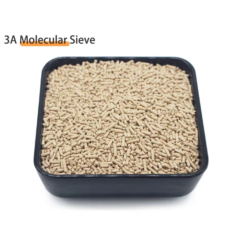
Molecular Sieve 4A and 13X with Tight PSD Control
4A and 13X molecular sieve grades with controlled particle size distribution (1st percentile above 1.5 mm) to minimize fines generation and bed-top channeling risk, ISO 22489 DCI capacity 21-23 wt% for 4A, with full batch COA covering PSD, attrition, and DCI capacity.
View Product Details →