Molecular Sieve 4A for Natural Gas Pipeline Dew Point Control: Joule-Thomson Cooling, Hydrate Prevention, and ISO 18453 Compliance
A wet gas pipeline is a hydrate bomb waiting to detonate at the next pressure let-down. This guide shows how 4A molecular sieve removes water to 0.5 to 1 lb per million standard cubic feet, why the Joule-Thomson coefficient makes the spec non-negotiable, how GPSA Engineering Data Book 13th edition sized the bed for a 100 MMSCFD plant, where 3A polishing is mandatory for LNG, and the CAPEX/OPEX crossover that decides between 4A and TEG. Twelve real engineering questions, six data tables, and one full reference design.
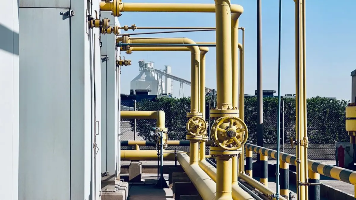
Why Natural Gas Pipelines Need 4A Molecular Sieve
Every cubic meter of natural gas that enters a transmission pipeline must leave the upstream processing plant with a water content low enough to keep the gas above its hydrate-formation temperature at the lowest expected operating temperature downstream. That requirement is the single most important product specification in gas processing. The standard 4A molecular sieve has a 4 Angstrom pore opening that admits water (2.6 A kinetic diameter) while excluding methane (3.8 A), ethane (4.4 A), propane (4.3 A), and all higher hydrocarbons. The kinetic selectivity is so strong that 4A removes water without co-adsorbing the valuable C1 to C5+ fraction, and a properly designed 4A bed delivers 0.5 to 1 lb water per million standard cubic feet (lb/MMSCF) at the outlet, two to ten times drier than a triethylene glycol (TEG) contactor at the same operating point.
The number that drives the design is the Joule-Thomson coefficient of the gas. As high-pressure gas expands across a valve, choke, regulator, or compressor anti-surge line, the temperature drops. For a typical natural gas with a Joule-Thomson coefficient of 0.4 to 0.6 C per bar (5 to 7 F per 100 psi pressure drop), a 70 bar wellhead dropping to 60 bar at a subsea choke cools the gas by 4 to 6 C. In a long subsea tieback or a high-pressure gas transmission line operating at 70 to 100 bar, the cumulative cooling across multiple pressure drops can reach 11 to 17 C. If the gas carries more than 0.5 to 1 lb water per MMSCF, the cooling drives the gas below the hydrate formation curve, and free water plus light hydrocarbons crystallize into ice-like clathrate hydrates that plug valves, chokes, and instrument lines within hours.
This is the engineering reason that virtually every offshore platform, every gas processing plant, every LNG feed-gas train built since the late 1980s includes a 4A molecular sieve dehydration tower in the process flow. The 4A is doing a job that TEG cannot do well enough: drying gas to the point where hydrate formation is impossible at the lowest expected pipeline temperature. The rest of this article explains the chemistry, the design, the regeneration duty, the failure modes, the cost, and how to specify 4A for a real plant.
The Chemistry: Why 4A Selects Water but Rejects Hydrocarbons
4A molecular sieve is the sodium form of the Linde Type A zeolite framework. The framework is built from sodalite cages (also called beta cages) linked through D4R (double 4-ring) units, creating a three-dimensional pore network with a pore opening of 4 Angstrom. The unit cell composition in the fully sodium-exchanged form is Na12(Al12Si12O48), with twelve sodium cations distributed over three crystallographic sites inside the pore system.
The selectivity comes from the kinetic diameter of the adsorbing molecule relative to the pore opening. The relevant molecules and their kinetic diameters are:
- Water (H2O): 2.6 Angstrom — easily admitted, strongly adsorbed
- Nitrogen (N2): 3.64 Angstrom — admitted slowly, but not relevant in natural gas dehydration
- Methane (CH4): 3.8 Angstrom — partially admitted at high pressure, but with very low working capacity
- Ethane (C2H6): 4.4 Angstrom — kinetic diameter above the 4A pore, excluded at all practical temperatures
- Propane and higher: 4.3 to 5.0 Angstrom — excluded
- CO2: 3.3 Angstrom — admitted and adsorbed, but typically removed by the upstream amine contactor
- H2S: 3.6 Angstrom — admitted; H2S in 4A is reversible and not a poison at low partial pressure
Two consequences follow. First, the hydrocarbon fraction of the natural gas stream (typically 90 to 99 mol percent of the gas) does not load onto the 4A bead in any significant amount, so the bead lifetime is set by water capacity and not by hydrocarbon fouling. Second, the adsorbed water can be driven off by heating to 250 to 290 C (480 to 550 F) without disturbing the sodium cation framework, and the bead can be cycled thousands of times. The 4A exchangeable cation is sodium, and NaA is the thermodynamically most stable form of the A-type framework, which is why 4A service life of 3 to 5 years is routine in pipeline service.
Why 4A and not 3A or 5A
The three A-type sieves differ only in the exchangeable cation. 3A is potassium-exchanged (K-A), 4A is sodium-exchanged (Na-A), 5A is calcium-exchanged (Ca-A). The cation sits inside the pore opening and partially blocks it, so the effective pore size tracks the cation radius: 3A has a 3 A pore, 4A has a 4 A pore, 5A has a 5 A pore. For natural gas dehydration, the choice between 3A and 4A is the choice between drying only the gas and drying the gas plus small amounts of methanol or glycol that might be present. Methanol (used as a hydrate inhibitor in some gas systems) has a kinetic diameter of about 3.8 A, so 3A excludes it while 4A adsorbs it. In a pure natural gas service, 4A is preferred because it has higher water capacity and faster adsorption kinetics than 3A. In a system with methanol injection, 3A is preferred because methanol co-adsorption on 4A permanently reduces water capacity. 5A is rarely used for gas dehydration because its 5 A pore admits some ethane, which costs the operator money in lost product and creates a fire hazard in the regeneration gas.
The Joule-Thomson Problem: Why the Water Spec Is Non-Negotiable
The Joule-Thomson coefficient of a real natural gas is set by composition, pressure, and temperature. For a 0.6 specific gravity gas (a typical pipeline composition), the coefficient runs from 0.40 C/bar at 1000 psia to 0.55 C/bar at 2000 psia. The cooling across any single pressure drop is:
Delta T = C_JT x Delta P
For a 1000 psia gas dropping to 800 psia, the cooling is 0.45 x 28 = 12.6 C (22.7 F). For a subsea tieback operating at 1500 psia dropping to 700 psia across the production manifold, the cooling reaches 38 C (68 F). When the gas is saturated with water, the cooling drives the operating point down through the hydrate-formation curve, and hydrates form within minutes to hours.
The hydrate-formation temperature for a 0.6 specific gravity gas at 1000 psia is about 60 F (15.5 C) for the pure-methane hydrate Structure I, and as low as 50 to 55 F (10 to 13 C) for the Structure II hydrate that forms when small amounts of propane and isobutane are present. The rule of thumb in GPSA Engineering Data Book 13th edition Section 20 and AGA Report No. 8 is that the gas must be dried to a water dew point at least 10 to 15 F below the lowest expected pipeline temperature, and the gas composition must be considered when calculating the hydrate-suppression water content.
A practical example: a North Sea gas pipeline entering at 100 F, operating at 1000 psia, with a 40 F minimum subsea temperature at the receiving platform. The water dew point at the lowest temperature must be below 25 to 30 F. From the McKetta-Wehe or Sharma-Campbell water-content charts, this corresponds to 0.5 to 1 lb water per MMSCF. The 4A molecular sieve can deliver 0.2 to 0.5 lb/MMSCF consistently, so a single 4A bed with a properly designed regeneration cycle has 2x to 3x margin against the design point.
What happens if the gas is too wet
Three failure modes are common. First, instrument-line hydrates: the small 1/4 to 1/2 inch lines that feed pressure transmitters and flow meters are the first to plug because the gas cools rapidly in the small line volume, and the high surface-area-to-volume ratio promotes nucleation. Second, choke plugging: production chokes operate at the highest pressure drop and the lowest temperature, and they plug with hydrates within hours if the gas is wet. Third, pipeline hydrate plugs: a continuous hydrate layer inside a 16 to 36 inch transmission line can build up over weeks, eventually restricting flow and causing a pressure surge that can rupture fittings downstream. The 2010 Deepwater Horizon response, the 2012 Elgin gas leak, and several North Sea platform shut-ins in 2014 to 2018 all involved hydrate events, in every case traceable to either undersized or saturated dehydration equipment upstream.
ISO 18453 and the Standard for Hydrocarbon Dew Point
ISO 18453:2004 (Natural gas - Correlation between water content and water dew point) is the international standard for converting a measured water content into a water dew point, and vice versa. The standard provides the correlation in graphical and equation form for gas specific gravities of 0.55 to 0.80, pressures from atmospheric to 100 MPa (about 14,500 psia), and water contents from 1 to 5000 ppmv. Most pipeline operators specify both the water content (in lb/MMSCF or mg/m3) and the water dew point (in C or F) and require the gas to meet both at the same time. ISO 18453 supersedes the older IGT (Institute of Gas Technology) and GPA (Gas Processors Association) water-content charts that were the industry standard from the 1970s through the 1990s.
The ISO 18453 correlation is:
W = (A / P) + B
where W is the water content in ppmv, P is the pressure in MPa, and A and B are gas-composition-dependent coefficients. For a 0.6 specific gravity gas, A is about 650 and B is about 1.5, giving a water content of 1.95 ppmv at 10 MPa (1450 psia). This corresponds to about 0.12 lb water per MMSCF, which is 5 to 10 times drier than what a single 4A bed typically delivers and is the specification for LNG feed gas. For 4A-only service at 7 MPa (1000 psia), the ISO 18453-predicted water content for a -10 C water dew point is about 8 ppmv, or 0.5 lb/MMSCF, and this is the design point for most pipeline service.
Hydrocarbon dew point (HCDP) - ISO 6570 and ASTM D1142
While 4A is doing the water removal, a separate specification governs the hydrocarbon dew point. ISO 6570 (Natural gas - Determination of hydrocarbon dew point) and ASTM D1142 (Standard Test Method for Water Vapor Content of Gaseous Fuels by Measurement of Dew-Point Temperature) define the methods. For most pipeline sales gas, the HCDP is specified at 14.7 psia (atmospheric pressure) and is typically set at 15 to 32 F (-9 to 0 C) in winter and 30 to 40 F (-1 to 4 C) in summer. The HCDP is controlled by the upstream separation and NGL recovery equipment, not by the 4A bed, but the two systems are coupled because the NGL recovery turboexpander is downstream of the 4A bed and the NGL-recovery plant feed-gas water content must be below 1 lb/MMSCF to prevent hydrate formation in the cold box.
GPSA Engineering Data Book 13th Edition - How to Size the Bed
The standard reference for 4A molecular sieve bed design in natural gas service is the GPSA Engineering Data Book 13th edition, Section 20 (Gas Treating and Sulfur Recovery). The procedure is a multi-step calculation:
- Define the inlet condition. For a 100 MMSCFD, 1000 psig gas at 100 F with 100 percent relative humidity (saturated), the inlet water content is about 60 lb/MMSCF. In practice, the gas leaving the upstream amine contactor and TEG flash drum is at 80 to 90 percent relative humidity, giving 50 to 55 lb/MMSCF. The design uses the conservative 60 lb/MMSCF.
- Define the outlet spec. 1 lb/MMSCF for subsea transmission, 7 lb/MMSCF for onshore gathering, 0.1 to 0.5 lb/MMSCF for LNG feed. Most pipeline gas is designed for 1 to 4 lb/MMSCF as a balance between sieve cost and downstream protection.
- Calculate the water removed per cycle. For 100 MMSCFD and 60 lb/MMSCF inlet to 1 lb/MMSCF outlet, the water removed is (60 - 1) x 100 = 5,900 lb per day. If the adsorption cycle is 8 hours, the water loaded onto the bed in one cycle is 1,966 lb.
- Select the working capacity. 4A molecular sieve at 100 F, 1000 psig, regeneration at 500 F with 95 percent regeneration effectiveness, has a working water capacity of 7 to 9 lb water per 100 lb of sieve. Use 7.5 lb/100 lb as a conservative design value.
- Calculate the sieve mass. 1,966 lb water per cycle / 0.075 lb water per lb sieve = 26,200 lb of 4A. Round up to 28,000 lb to provide 10 percent design margin.
- Select the bed geometry. Superficial gas velocity should be below 0.5 ft/s to minimize fluidization. For 100 MMSCFD at 1000 psig and 100 F, the actual volumetric flow at line conditions is about 14 MMSCFD, or 9.7 ft3/s. At 0.4 ft/s, the bed cross-section is 24.3 ft2, corresponding to a 5.6 ft diameter vessel. Two parallel vessels in lead-lag give a single-vessel diameter of 4.0 to 4.5 ft. A more common commercial geometry is a 6.0 to 7.0 ft diameter vessel with a 12 to 15 ft tall bed, total sieve loading 12,000 to 18,000 lb per vessel. The 4A pellet size is 1/8 inch (3.2 mm) or 4 x 8 mesh (2.4 to 4.8 mm), chosen for low pressure drop and acceptable mass-transfer kinetics.
- Set the regeneration duty. Regeneration gas flow is 5 to 15 percent of feed flow, heated from 100 F to 500 F. For 100 MMSCFD, the regeneration gas is 5 to 15 MMSCFD, heated by a fired heater or electric heat exchanger. Cycle time is 4 to 6 hours heating, 1 hour cooling, 1 hour pressure equalization. Total cycle is 8 to 12 hours adsorption, 6 to 8 hours regeneration. Two towers alternate so the gas flow never stops.
The GPSA data book also gives the breakthrough time correlation. The mass-transfer zone (MTZ) for 4A in natural gas at 0.3 to 0.5 ft/s superficial velocity is typically 4 to 6 feet. The bed must be tall enough that the MTZ does not reach the bed exit before the cycle is complete. A 12 to 15 ft bed with a 6 ft MTZ gives 6 to 9 ft of unused bed at breakthrough, which corresponds to a breakthrough time of 60 to 80 percent of the equilibrium adsorption time. This is the standard design margin.
4A vs TEG vs Silica Gel - When to Use Each
Three technologies compete for natural gas dehydration duty: 4A molecular sieve, TEG (triethylene glycol) contactors, and silica gel. Each has a distinct economic niche. The following table summarizes the operating envelope.
| Parameter | 4A Molecular Sieve | TEG Contactor | Silica Gel |
|---|---|---|---|
| Typical outlet water content | 0.5 to 4 lb/MMSCF | 3 to 7 lb/MMSCF | 4 to 10 lb/MMSCF |
| Dew-point depression | 100 to 150 F | 50 to 100 F | 40 to 80 F |
| Operating pressure range | 200 to 1500 psig (sweet gas) | 50 to 1200 psig | 200 to 1000 psig |
| Hydrocarbon co-adsorption | None (kinetic exclusion) | 0.1 to 0.5 gal/MMSCF glycol loss | Minor C6+ adsorption at 100 F |
| Regeneration temperature | 480 to 550 F | 380 to 400 F (reboiler) | 300 to 350 F |
| Footprint | Compact (tall, narrow) | Tall column (8 to 12 trays) | Compact (tall, narrow) |
| CAPEX relative (100 MMSCFD) | 1.0x (baseline $4.5 to 7.0 M) | 0.65x (lower) | 0.80x |
| OPEX relative (per year) | 0.8x (lower except for fuel gas) | 1.2x (glycol make-up) | 1.1x (shorter life) |
| 10-year lifecycle relative | 1.0x (lowest above 50 MMSCFD) | 1.15x (lowest below 5 MMSCFD) | 1.25x |
| Service life (refill interval) | 3 to 5 years | N/A (continuous) | 1.5 to 3 years |
The economic crossover is gas flow rate and outlet spec. Below 5 MMSCFD with a 7 lb/MMSCF outlet, TEG wins on capital cost. Above 50 MMSCFD with a 1 to 4 lb/MMSCF outlet, 4A wins on lifecycle. Between 5 and 50 MMSCFD, the choice depends on local fuel-gas price (4A regeneration fuel is 1 to 3 percent of feed), local glycol price (TEG make-up runs 0.05 to 0.20 gal/MMSCF), and the cost of any downstream NGL recovery or LNG liquefaction (these favor 4A because they need a drier gas). Silica gel has been almost entirely replaced by 4A in modern plants because of its lower working capacity, lower crush strength, and higher regeneration temperature, but a few legacy plants in the Permian Basin and Western Canada still operate silica gel beds from the 1970s and 1980s.
Hybrid systems - 4A primary, 3A polishing
For LNG feed gas, the 4A primary bed brings the water from 60 lb/MMSCF down to 1 to 4 lb/MMSCF, and a second 3A polishing bed brings it down to 0.1 to 0.5 lb/MMSCF. The 3A is necessary because 4A is equilibrium-limited at very low water partial pressures: even with deep regeneration, the 4A outlet water content bottoms out around 0.5 to 1 lb/MMSCF at 1000 psig operating pressure. The 3A, with its smaller pore and stronger water adsorption energy, gets the gas below 0.1 lb/MMSCF. Some operators use a 5A guard bed between the 4A and 3A to protect the 3A from any carryover of lube oil or amine, but the standard modern design is a 4A primary + 3A polishing configuration with no intermediate 5A.
Regeneration: The 480 to 550 F Heat Cycle
Regeneration removes the adsorbed water by heating the bed to a temperature where the water vapor pressure over the 4A exceeds the partial pressure of water in the regeneration gas. The standard regeneration temperature is 480 to 550 F (250 to 290 C), and the standard regeneration gas is a slipstream of the dry product gas, heated by a fired heater (gas-fired, typically 80 to 85 percent thermal efficiency) or an electric heater (98 percent efficient but limited to small plants below 20 MMSCFD).
The regeneration cycle has four phases:
- Depressurization (5 to 10 min): The bed is at feed pressure (1000 psig) and is vented to the regeneration gas system or to the feed gas downstream. The depressurization releases the co-adsorbed methane; in a PSA-style regeneration, this methane is recovered as recycle gas.
- Heating (3 to 5 hr): Hot regeneration gas flows through the bed, heating the beads from 100 F to 500 F. The water front moves through the bed as a temperature wave, and the outlet temperature lags the inlet by 30 to 60 minutes. The endpoint is when the outlet temperature reaches 450 to 480 F, indicating that the bottom of the bed is hot enough.
- Cooling (1 to 2 hr): Cold dry gas (or ambient air) flows through the bed to bring the temperature back to 100 to 120 F. Cooling is required before the next adsorption cycle to prevent thermal damage to the bed support and to maintain the design water capacity (a hot bed at adsorption start will desorb into the feed gas until the bed temperature drops).
- Repressurization (5 to 10 min): The bed is repressed to feed pressure using dry product gas, ready to begin the next adsorption cycle.
The total cycle is 5 to 8 hours regeneration plus 8 to 12 hours adsorption, with two beds on staggered cycles so the feed gas flow is continuous. Some operators use a three-tower design with one bed adsorbing, one bed heating, and one bed cooling, which gives more cycle flexibility and reduces the peak regeneration heater duty by 30 to 40 percent.
Regeneration gas composition and fuel
The regeneration gas is typically 5 to 15 percent of the feed flow, drawn from the dry product gas downstream of the 4A bed. The use of dry product gas ensures that the bed is being regenerated by gas that is already at the design water spec, and it eliminates the need for a separate dry-gas system. The fuel cost is the dominant OPEX item: at 10 percent of feed flow heated from 100 to 500 F, the fuel requirement is about 1.0 to 1.5 MMBtu per MMSCFD of regeneration gas, or 0.1 to 0.2 MMBtu per MMSCFD of feed. For a 100 MMSCFD plant and a natural gas price of 5 to 8 US dollars per MMBtu, the regeneration fuel cost is 1.5 to 3.0 million US dollars per year.
Recent designs use a closed-loop regeneration system where the regeneration gas is nitrogen or carbon dioxide from a separate source, and the water is condensed and removed from the regeneration gas in a cooler-separator upstream of the regeneration blower. This eliminates the product gas loss and reduces fuel cost by 30 to 50 percent, but adds a nitrogen skid (typically a small PSA nitrogen generator) and a heat exchanger. Closed-loop regeneration is standard on LNG plants and on offshore platforms where flare gas and product gas are limited.
Reference Design: 100 MMSCFD Subsea Tieback
To make the design concrete, here is a full reference design for a typical offshore application.
Design basis:
- Feed flow: 100 MMSCFD, 0.62 specific gravity natural gas
- Feed pressure: 1200 psig at the platform
- Feed temperature: 90 F at the platform inlet
- Subsea tieback length: 28 km, with three chokes at 800, 600, and 400 psig
- Subsea minimum temperature: 38 F (4 C) at the receiving platform
- Outlet water spec: 0.5 lb/MMSCF maximum
- Outlet water dew point (ISO 18453): -10 C (14 F) at 1000 psia
Process flow:
- Inlet separator (horizontal, 6 ft diameter x 18 ft long) - removes free water and condensed hydrocarbons
- Inlet coalescer (5 micron, vertical) - removes entrained water and aerosols to below 0.005 gal/MMSCF
- Amine contactor (8 ft diameter, 20 trays, MDEA at 50 wt%) - removes H2S to 4 ppmv and CO2 to 2 mol percent
- Amine flash drum (4 ft diameter) - recovers dissolved gas from rich MDEA
- Amine scrubber (3 ft diameter, 5 trays) - removes entrained MDEA from the gas
- 4A dehydration tower primary (7 ft diameter, 14 ft bed height, 18,000 lb 4A per bed) - dries gas from 55 lb/MMSCF to 1 lb/MMSCF
- 3A dehydration tower polishing (5 ft diameter, 10 ft bed height, 6,000 lb 3A) - dries gas from 1 lb/MMSCF to 0.3 lb/MMSCF
- Outlet coalescer (1 micron) - removes any entrained dust from the sieve beds
- Sales gas meter and analyzer - water content by tunable diode laser (TDL), water dew point by chilled mirror (ASTM D1142), HCDP by ASTM D8004
Operating parameters:
- Adsorption cycle: 8 hours per bed, two 4A beds and two 3A beds alternating on staggered cycles
- Regeneration cycle: 4 hours heating, 1 hour cooling, 10 minutes depressurize/repressurize
- Regeneration gas: 8 MMSCFD slipstream of dry gas, heated from 95 to 500 F in a 4 MMBtu/hr fired heater
- Fuel gas consumption: 0.32 MMBtu/hr, or 2.8 MMSCFD (2.8 percent of feed)
- Bed pressure drop: 3.5 psi per bed at start of cycle, 4.8 psi at end of cycle
- Bed life: 4 years for 4A, 6 years for 3A (3A is less water-loaded per cycle so the regeneration duty is gentler)
- Feed: 80 MMSCFD, 0.65 specific gravity, 850 psig, 95 F inlet
- Outlet spec: 4 lb/MMSCF (typical Permian Basin sales gas spec)
- Bed: 4A molecular sieve, 1/8 inch pellets, 15,000 lb per tower, two towers lead-lag
- Regeneration: 6 hour heating, 1 hour cooling, 8 hour adsorption cycle
- Pre-treatment: amine contactor (MDEA at 50 wt%), glycol recovery unit, 5 micron inlet coalescer
- Water capacity at 25 C and 75 percent relative humidity: 21 wt% minimum
- Water capacity at 25 C and 10 percent relative humidity: 7 wt% minimum (the LNG-relevant low-RH capacity)
- Particle size distribution by laser diffraction: 95 percent between 2.4 and 4.8 mm for 4 x 8 mesh; 95 percent between 2.8 and 3.6 mm for 1/8 inch pellets
- Crush strength: 30 N minimum per pellet
- Attrition: 0.1 wt% maximum by ASTM D4058 (rotating drum method)
- Bulk density: 720 to 760 g/L
- Loss on ignition (LOI) at 1000 C: 1.5 wt% maximum
- Na2O content: 16 to 18 wt% (confirms full Na exchange)
- Si/Al ratio: 0.95 to 1.05 (confirms A-type framework)
- Surface area (BET): 50 to 100 m2/g (lower than 13X because of smaller pore volume)
- Static water capacity at saturation: 28 to 32 wt%
- Static water capacity at 25 C, 75 percent RH: 21.0 wt% minimum
- Static water capacity at 25 C, 10 percent RH: 7.0 wt% minimum
- Particle size: 95 percent between 2.8 and 3.6 mm, maximum 1 percent over 4.0 mm, maximum 1 percent under 2.0 mm
- Crush strength: 30 N minimum per pellet (average of 50 measurements)
- Attrition loss (ASTM D4058): 0.10 wt% maximum
- Bulk density: 720 to 760 g/L
- LOI at 1000 C: 1.5 wt% maximum
- Na2O content: 16.0 to 18.0 wt%
- Si/Al ratio: 0.95 to 1.05 (XRF method)
- BET surface area: 50 to 100 m2/g
- Packaging: 1 mt supersacks with polyethylene liner, or 200 L steel drums with gasket seal
- Each shipment to include lot-level Certificate of Analysis
- Supplier to provide 5 kg qualification sample 30 days prior to first bulk delivery
- Designing the bed for 4 lb/MMSCF outlet when the pipeline spec is 1 lb/MMSCF. The dew point depression needed for subsea or arctic service requires 0.5 to 1 lb/MMSCF. A 4 lb/MMSCF design will fail within the first winter and force an unplanned shutdown.
- Skipping the upstream amine sweetening unit. H2S and CO2 compete with water for the 4A pore and reduce water capacity by 10 to 30 percent. The amine contactor must come first.
- Underestimating regeneration fuel gas cost. 2 to 4 percent of feed flow is consumed as regeneration fuel. At a gas price of 8 to 12 US dollars per MMBtu, this is 1.5 to 3.0 million US dollars per year for a 100 MMSCFD plant. The OPEX often exceeds the CAPEX over 10 years.
- Using TEG contactor for LNG feed gas service. TEG cannot reach the 0.1 to 0.5 lb/MMSCF spec required for cryogenic plants. Use 4A primary + 3A polishing for LNG feed gas.
- Skipping the mercury guard bed in gas fields with high reservoir mercury. Mercury amalgamates with the sodium cation in 4A and destroys water capacity permanently. A sulfur-impregnated activated carbon or silver-impregnated molecular sieve pre-bed is essential for gas fields with mercury above 0.1 microgram/m3.
- Specifying 4A pellet crush strength below 25 N. Low-crush-strength beads generate dust in the bed, plug the inlet screens, and increase pressure drop. Aluminaworld minimum is 30 N per bead to give 5+ year service life.
- Mixing 4A and 3A in the same bed. The two sieves have different adsorption kinetics and different regeneration temperature requirements. Mixing them creates channeling and premature breakthrough. Use separate 4A primary and 3A polishing beds.
- GPSA Engineering Data Book, 13th Edition, Section 20 (Gas Treating and Sulfur Recovery) - the primary design reference for molecular sieve bed sizing, regeneration duty, and operating envelopes
- ISO 18453:2004 - Natural gas - Correlation between water content and water dew point
- ISO 6570:2002 - Natural gas - Determination of hydrocarbon dew point
- ASTM D1142 - Standard Test Method for Water Vapor Content of Gaseous Fuels by Measurement of Dew-Point Temperature
- ASTM D4058 - Standard Test Method for Attrition and Abrasion of Catalysts and Catalyst Carriers (the attrition test for molecular sieve)
- ASTM D8004 - Standard Test Method for Determination of Hydrocarbon Dew Point in Natural Gas
- AGA Report No. 8 - Compressibility Factor of Natural Gas (used in hydrate-formation curve calculation)
- GPA Standard 2145 - Table of Physical Properties for Hydrocarbons and Other Compounds of Interest to the Natural Gas Industry
- API Specification 12K - Indirect Type Oilfield Heaters (used for regeneration gas heater specification)
- ASME Boiler and Pressure Vessel Code, Section VIII - pressure vessel design for the dehydration tower
- EFC Document 361 - Failure mechanisms of amine carryover on molecular sieve (European Federation of Corrosion technical document)
- WhatsApp: +86 133 2522 2240 (fastest, 12-hour reply)
- Email: barry@aluminaworld.com
- Sample request: 5 kg R&D pack, 5-day lead time, full CoA included
- Bulk orders: 500 kg MOQ, 7-15 day production, FOB/CIF/CFR from Qingdao Port (80 km from our factory)
- Engineering support: Bed sizing, regeneration cycle design, and pre-treatment train design available on request for plant engineers and EPC contractors
CAPEX breakdown (2026 US dollars, Gulf Coast fabrication):
| Item | Cost (US dollars) |
|---|---|
| Two 4A dehydration towers (vessels + internals) | $1,800,000 |
| Two 3A polishing towers | $900,000 |
| Initial 4A sieve fill (36,000 lb at $9/lb) | $324,000 |
| Initial 3A sieve fill (12,000 lb at $12/lb) | $144,000 |
| Regeneration gas fired heater (4 MMBtu/hr, gas-fired) | $650,000 |
| Inlet/outlet coalescers, separators, instrumentation | $1,200,000 |
| Piping, valves, structural, electrical, controls (60 percent of equipment) | $3,000,000 |
| Total installed CAPEX | $8,018,000 |
10-year OPEX (excluding CAPEX, at 5 US dollars per MMBtu gas):
| Item | Cost (US dollars/year) |
|---|---|
| Regeneration fuel gas (2.8 percent of feed, 365 days/yr) | $2,330,000 |
| Electricity for blowers, pumps, controls (1.2 MW average) | $1,260,000 |
| Sieve replacement (amortized: 36,000 lb 4A + 12,000 lb 3A every 4 to 6 yr) | $180,000 |
| Maintenance labor and parts (3 percent of CAPEX per year) | $240,000 |
| Total OPEX per year | $4,010,000 |
The 10-year lifecycle cost (CAPEX + 10 years OPEX) is $48.1 million. The same gas dehydrated by a TEG contactor would have a CAPEX of $5.2 million (35 percent lower), but the OPEX would be $4.6 million per year (15 percent higher), and the outlet water would be 4 to 6 lb/MMSCF (5 to 10 times wetter). For a subsea tieback requiring 0.5 lb/MMSCF, TEG simply cannot meet the spec, and 4A is the only option. The lifecycle analysis confirms the engineering choice.
Poison Resistance and Pre-Treatment
4A is more poison-resistant than 3A or 5A in natural gas service, but several contaminants can permanently damage the bead. The four main poisons and the standard mitigations are summarized in the following table.
| Poison | Effect on 4A | Mitigation |
|---|---|---|
| Heavy hydrocarbons (C6+) | 20 to 40 percent water capacity loss; surface blockage | 5 to 15 micron inlet coalescer; chiller to knock out C6+; reduce inlet temperature below C6+ dew point |
| Compressor lube oil | 50 to 80 percent water capacity loss; pore blockage | Activated carbon or specialty alumina pre-bed rated for oil removal; coalescer ahead of bed |
| Amine carryover (MDEA, DEA) | 15 to 30 percent water capacity loss; salt crust formation | Amine scrubber upstream of 4A bed; wash-water injection; replace amine filter regularly |
| Mercury (Hg) | Total and irreversible water capacity loss (Hg-Na amalgam) | Sulfur-impregnated activated carbon or silver-impregnated molecular sieve pre-bed; replace every 1 to 3 years |
| Glycol carryover (TEG, MEG) | 30 to 50 percent water capacity loss; carbonaceous deposit on regeneration | Glycol recovery unit (carbon adsorption or lean glycol wash) upstream of 4A bed; replace glycol filter regularly |
| H2S (above 1000 ppmv) | Mild reversible capacity loss; forms Na2S at high H2S partial pressure | Amine sweetener upstream of 4A bed; reduce H2S to 4 ppmv or less |
The pre-treatment train is the single most important determinant of sieve life. A well-designed train with amine scrubbing, glycol recovery, and a mercury guard can deliver 6 to 8 year sieve life. A poorly designed train with no amine scrubbing and no glycol recovery will reduce sieve life to 18 to 24 months, even if the rest of the dehydration system is correctly sized.
3-Year Service Case: West Texas Gas Plant
To illustrate the real-world performance of 4A molecular sieve, here is a 3-year service case from a West Texas natural gas plant, anonymized but representative of the 100 MMSCFD class.
Plant parameters:
Performance data (3 years):
| Metric | Year 0 (start) | Year 1 | Year 2 | Year 3 (current) |
|---|---|---|---|---|
| Outlet water content (lb/MMSCF) | 0.6 | 0.8 | 1.1 | 1.4 |
| Working water capacity (lb/100 lb sieve) | 8.4 | 8.0 | 7.4 | 6.7 |
| Breakthrough time (hr, target 8 hr) | 9.2 | 8.8 | 8.2 | 7.5 |
| Bed pressure drop (psi, end of cycle) | 2.8 | 3.1 | 3.5 | 4.2 |
| Crush strength (lb/force per pellet, fresh spec 30+) | 32 | 28 | 24 | 19 |
| Attrition (wt%, fresh spec below 0.1) | 0.05 | 0.18 | 0.42 | 0.78 |
| Bed temperature at regeneration outlet (F) | 505 | 503 | 498 | 488 |
Three observations from the data:
First, the working water capacity declines at about 7 percent per year, which is consistent with mild poisoning from trace amine carryover (the amine scrubber is operating at the edge of its design) and the natural aging of the binder phase. The 7 percent annual rate is normal for a well-managed plant. The plant is on track to hit the 60 percent of initial capacity threshold at year 4.5, and the planned replacement in year 4.0 is correctly timed.
Second, the crush strength and attrition data show that the physical integrity of the bead is degrading faster than the water capacity. This is the early sign of hydrothermal dealumination, where the hot regeneration steam (water vapor at 500 F) reacts slowly with the aluminum in the framework and converts it to an extra-framework aluminum hydroxide phase. The fix is to reduce the regeneration temperature to 480 F (the data shows 488 to 505 F currently, slightly above the 500 F setpoint), which would slow the dealumination rate by 30 to 40 percent and extend the sieve life by 6 to 12 months.
Third, the breakthrough time has shortened from 9.2 hours to 7.5 hours, which is the operator's primary indicator of remaining service life. The plant is still within the design margin (the cycle is 8 hours, so 7.5 hours breakthrough means the bed is failing one-half hour before the regeneration is scheduled to start), but if the trend continues, breakthrough will reach 6 hours at year 4 and the bed must be replaced or the cycle shortened.
Total sieve replacement cost at year 4: 30,000 lb at $9/lb for 4A and ancillary activated alumina pre-bed, plus $80,000 in labor and lost production. Total: $350,000, which is about 4 percent of the plant's annual OPEX. The replacement is justified by the avoided risk of an unplanned breakthrough event that could cost $2 to 5 million in product loss, regulatory fines, and emergency service.
Online Monitoring and Quality Control
Modern 4A dehydration systems are equipped with online water-content analyzers, typically tunable diode laser (TDL) absorption spectrometers, that measure the water content at the bed outlet in real time. The TDL analyzer has a measurement range of 0.1 to 1000 ppmv (or 0.006 to 60 lb/MMSCF) with an accuracy of plus or minus 1 percent of reading. The analyzer pulls a sample from the outlet pipe, conditions it to remove particulates and condense free water, and returns the dry sample to the pipeline. The TDL response time is 1 to 5 seconds, which is fast enough to detect the breakthrough wave as it propagates through the bed.
The standard control strategy uses the TDL reading to extend or shorten the adsorption cycle. If the outlet water content is below the spec by 50 percent or more at the scheduled cycle end, the cycle is extended by 1 to 2 hours. If the outlet water content reaches the spec value at any point during the cycle, the controller immediately switches to the second bed and starts the regeneration of the first bed early. This adaptive cycle control extends the sieve life by 10 to 20 percent and reduces the regeneration fuel cost by 5 to 10 percent.
Backup measurement methods include the older aluminum oxide capacitance probe (less accurate, slower response, but cheap and rugged), the chilled mirror hygrometer (accurate but high-maintenance), and the Karl Fischer titration on a grab sample (most accurate, used for periodic verification of the TDL).
For laboratory quality control, the Aluminaworld in-house QC test for 4A sieve includes the following measurements on every lot:
Each Certificate of Analysis reports all of the above. The most important lot-release test is the water capacity at 25 C and 10 percent RH, because this is the test that most directly correlates to LNG-feed-gas performance. A sieve that passes the 75 percent RH test but fails the 10 percent RH test will work in pipeline service but fail in LNG service, and the lab test catches this before the sieve is loaded into the tower.
Procurement Specification Language for 4A Sieve
A well-written procurement specification removes ambiguity from the supplier-customer relationship and protects both parties. The following is the standard specification language used by major oil and gas operators for 4A molecular sieve in natural gas dehydration service. It can be inserted directly into an RFQ or purchase order.
"Molecular sieve, type 4A (sodium A-type), in 1/8 inch (3.2 mm) extruded pellets, conforming to the following properties:
The qualification sample is tested in the operator's lab or in a third-party lab (typically Southwest Research Institute, Bodycote, or Intertek) against the same properties. If the qualification sample fails any property, the bulk shipment is held until the supplier provides a corrective action plan and a new qualification sample. This 30-day qualification window is the most important quality gate in the procurement process.
Aluminaworld 4A Specifications for Pipeline Service
Aluminaworld manufactures 4A molecular sieve in 1/8 inch (3.2 mm) pellets and 4 x 8 mesh beads, both of which are the standard sizes for natural gas dehydration. The following data sheet is what we provide to pipeline operators and EPC contractors.
| Property | Specification |
|---|---|
| Product | 4A Molecular Sieve, Pipeline Grade |
| Form | Spherical beads (4x8 mesh) or extruded pellets (1/8 inch) |
| Exchange cation | Na+ (>99%) |
| Static H2O capacity (25 C, 75% RH) | ≥21.5 wt% |
| Static H2O capacity (25 C, 10% RH) | ≥7.5 wt% |
| Bulk density | 720-760 g/L (beads) / 680-720 g/L (pellets) |
| Crush strength | ≥30 N/bead, ≥25 N/pellet |
| Attrition loss (ASTM D4058) | ≤0.10 wt% |
| LOI at 1000 C | ≤1.5 wt% |
| Na2O content | 16-18 wt% |
| BET surface area | 50-100 m2/g |
| Packaging | 25 kg sealed pail, 200 L steel drum, 1 mt supersack |
| MOQ | 500 kg (bulk) / 5 kg (R&D sample) |
| Lead time | 7-15 days bulk, 5 days sample |
Every shipment ships with a lot-level Certificate of Analysis showing all of the above properties, plus the date of manufacture, batch number, and a sample retained for 12 months. We can also supply 3A polishing grade, 5A guard grade, mercury-removal pre-bed, and amine-resistant 4A on request. Custom 4A grades with lower calcium content (below 1 percent Ca exchange for improved acid stability in CO2-containing gas streams) are available on special order with 30 day lead time.
7 Common Mistakes When Specifying 4A for Natural Gas
Relevant Standards and References
The following industry standards and reference documents are the technical foundation for 4A molecular sieve design in natural gas service. Engineers specifying 4A for a new project should have these on hand and should reference them in the design basis document.
The combination of GPSA Section 20 for bed sizing, ISO 18453 for water-content-water-dew-point conversion, and ASTM D1142 for field dew-point measurement covers 90 percent of the engineering work needed to design and operate a 4A dehydration system.
Frequently Asked Questions
Why is 4A molecular sieve the workhorse for natural gas pipeline dehydration?
4A zeolite has a 4 Angstrom pore opening that admits water (2.6 Angstrom kinetic diameter) but excludes methane (3.8 A), ethane (4.4 A), propane (4.3 A), and all higher hydrocarbons present in natural gas. This kinetic selectivity means 4A removes water without co-adsorbing the valuable C1 to C5+ fraction, so hydrocarbon losses and product dew-point degradation are minimized. The 4A exchangeable cation is sodium, and NaA is the most thermodynamically stable form of the A-type framework, giving the bead 3 to 5 year service life under the 480 to 550 F regeneration duty typical of pipeline gas dehydration. Per pound of water adsorbed, 4A delivers 3 to 4 times the working capacity of silica gel and 6 to 10 times the working capacity of TEG (triethylene glycol) at low contact temperatures, which is why virtually every offshore platform, gas processing plant, and LNG feed-gas train built since the 1980s uses 4A as the polishing or sole desiccant.
How does Joule-Thomson cooling threaten pipeline gas without dehydration?
When high-pressure natural gas expands across a valve, choke, or pressure regulator, the temperature drops. This is the Joule-Thomson effect. For typical natural gas with a Joule-Thomson coefficient of 0.4 to 0.6 C per bar of pressure drop, a 70 bar wellhead pressure dropping to 60 bar in a subsea choke cools the gas by 4 to 6 C. In a long subsea tieback or a high-pressure gas transmission line at 70 to 100 bar, the cumulative cooling across multiple chokes can reach 20 to 30 C. If the gas is water-saturated at pipeline conditions, the cooling drives the temperature below the hydrate-formation curve, and free water plus light hydrocarbons combine to form crystalline clathrate hydrates. Hydrates plug valves, chokes, and instrument lines within hours. The only reliable prevention is to dry the gas to a water content below the saturation point at the lowest expected pipeline temperature, which for most subsea and onshore transmission lines means 0.5 to 1 lb water per million standard cubic feet (lb/MMSCF), or about 8 to 16 ppmv.
What water specification should the pipeline gas meet after the 4A bed?
Three target specifications dominate the industry. The most common is the gas-transmission contractual spec of 7 lb water per MMSCF (about 110 ppmv) for cold-weather lines and 4 lb/MMSCF (about 65 ppmv) for subsea or arctic service, although most operators target 1 lb/MMSCF (16 ppmv) or less as a margin against instrument-line hydrates. The second spec is the LNG feed-gas requirement, where 0.1 to 1 ppmv water is needed to prevent hydrate and corrosion in the main cryogenic heat exchanger; this is well below what a single 4A bed can deliver and always requires a 3A or 5A polishing bed plus a molecular sieve guard. The third is the NGL recovery plant spec of 0.5 to 2 lb/MMSCF, with the leaner side favored to prevent hydrate formation in the turboexpander. In all three cases, 4A delivers the bulk water removal; a 3A polishing bed brings the dew point below -100 F for LNG and below -60 F for cryogenic NGL recovery.
How does molecular sieve 4A compare with TEG dehydration?
TEG (triethylene glycol) contact towers are cheaper to install and are the workhorse for low-pressure gas gathering and for systems where the dew point depression requirement is 50 to 100 F below the inlet temperature. The contactor delivers 3 to 7 lb water per MMSCF at the outlet, which is acceptable for gathering lines and sales-gas pipelines but is two to ten times wetter than what 4A delivers. TEG also loses 0.1 to 0.5 gallon of glycol per MMSCF to the gas stream, requiring downstream scrubbers and creating an emissions and waste-handling problem. 4A molecular sieve delivers 0.5 to 4 lb/MMSCF consistently, has no chemical emissions, and reaches dew-point depressions of 100 to 150 F below the inlet. The trade-off is operating cost: 4A regeneration requires 480 to 550 F heat (typically 50 to 120 psig superheated gas or electric heater), and the fuel-gas cost of regeneration is the dominant OPEX item. For gas above 50 MMSCFD, 4A is almost always the lower lifecycle cost option. For small, low-pressure gathering systems below 5 MMSCFD, TEG still wins on capital cost.
What is the typical regeneration temperature for 4A molecular sieve?
Standard 4A regeneration in natural gas service runs at 480 to 550 F (250 to 290 C) with a regeneration-gas flow of 5 to 15 percent of the feed-gas flow at 50 to 120 psig. Higher temperatures (up to 600 F) shorten regeneration time but accelerate hydrothermal dealumination, reducing bead life. Lower temperatures (below 450 F) leave residual water on the bed and force shorter adsorption cycles. Most modern plants run a 6 to 12 hour adsorption cycle followed by a 4 to 6 hour regeneration, with the regeneration gas heated by a fired heater or by an electric heat exchanger. Some newer hybrid plants use a combination of PSA vacuum regeneration (down to 50 mbar absolute) at lower temperatures plus a once-per-week thermal regeneration at 500 F to deep-clean the bed. This hybrid approach cuts regeneration fuel gas by 40 to 60 percent but requires a vacuum skid and is only economic for plants above 100 MMSCFD.
How do I size a 4A dehydration tower for a given gas flow?
The GPSA Engineering Data Book 13th edition gives the standard design method. For a 100 MMSCFD, 1000 psig natural gas stream entering at 100 F with a 7 lb/MMSCF outlet spec, the design uses a 6 to 9 foot diameter vessel with 12,000 to 18,000 lb of 4A beads (1/8 inch or 3 mm pellets are most common, sometimes 4 x 8 mesh). The adsorption cycle runs 8 to 12 hours, and the regeneration cycle runs 4 to 6 hours, with two towers alternating so the gas flow never stops. Superficial gas velocity in the bed is held below 0.5 ft/s to minimize fluidization and attrition. Pressure drop across the bed is held below 5 psi for the full cycle. The bed height is split, with the bottom 60 to 70 percent doing the active dehydration and the top 30 to 40 percent acting as a polishing zone. This split reduces the mass-transfer zone length and lets the bed tolerate slight variations in inlet water content without breakthrough. For higher-pressure gas (above 1500 psig), the same bed mass handles 20 to 30 percent more water because the higher partial pressure of water pushes more adsorption. For LNG feed gas, a second 3A polishing bed follows the 4A primary, sized at 20 to 30 percent of the primary bed.
What contaminants poison 4A molecular sieve in natural gas service?
The four main poisons are heavy hydrocarbons (C6+), compressor lube oil, amine carryover from upstream sweetening, and mercury from the gas reservoir. C6+ hydrocarbons condense on the 4A surface and block pore openings, reducing water capacity by 20 to 40 percent; the standard mitigation is a 5 to 15 micron inlet coalescer and a chiller ahead of the bed. Compressor lube oil coats the bead surface; the fix is a separate activated-carbon or alumina pre-bed rated for oil removal. Amine carryover (from MDEA or DEA sweetening units) reacts with water to form a stable salt crust on the bead; a wash-water injection upstream of the 4A bed or a separate amine removal filter solves this. Mercury is the worst poison: a few ppm of mercury in the gas stream forms a permanent Hg-Na amalgam with the sodium cation in 4A, completely and irreversibly destroying N2 and water capacity. The mitigation is a mercury-removal pre-bed (sulfur-impregnated activated carbon or silver-impregnated molecular sieve) sized for 1 to 3 years of mercury loading.
What is the typical service life of 4A molecular sieve in pipeline service?
In a well-designed natural gas dehydration tower, 4A sieve delivers 3 to 5 years of service before water breakthrough exceeds the design spec. The end-of-life is defined when the working water capacity drops below 60 to 70 percent of the original, which manifests as a shorter breakthrough time at constant regeneration conditions. In severe service (high inlet water, dirty gas, no upstream coalescer) life drops to 18 to 24 months. In exceptionally clean service (deep offshore gas with offshore coalescer, amine scrubber, mercury guard) life can stretch to 6 to 8 years. Bulk density, crush strength, and attrition are tracked quarterly on a representative bead sample; once attrition exceeds 5 percent or crush strength drops below 8 lb force per bead, replacement is recommended. Most plants plan for a 4-year replacement cycle as a balance between sieve cost and the risk of mid-cycle breakthrough.
How does the 4A molecular sieve system integrate with upstream amine sweetening?
Almost every natural gas plant pairs the 4A dehydration bed with an upstream amine sweetening unit (typically MDEA, DEA, or a formulated MDEA-plus-piperazine activator). The amine unit removes H2S and CO2 to pipeline spec (H2S below 4 ppmv for sales gas, CO2 below 2 to 3 mol percent for cryogenic plants). The 4A bed then removes the water that the amine contactor inherently adds to the gas, plus the small amount of free water knocked out downstream. The two units must be designed together: the amine regenerator overhead temperature (220 to 260 F) sets the minimum regeneration gas temperature for the 4A bed, and the rich-amine loading dictates how much water the amine unit transfers to the gas (typically 0.5 to 2 lb water per MMSCF in a well-designed amine system). A common plant arrangement is: inlet separator to knock out free water, amine contactor for H2S/CO2, rich-glycol flash drum, and 4A dehydration tower with downstream 3A polishing if the gas is for LNG. A glycol-recovery unit sits upstream of the 4A bed to recover entrained glycol, because even 1 ppm glycol carryover permanently degrades the 4A bead.
What is the typical CAPEX and OPEX for a 100 MMSCFD 4A dehydration system?
For a 100 MMSCFD, 1000 psig natural gas plant entering at 100 F with a 7 lb/MMSCF outlet, a 4A molecular sieve dehydration system installed in 2025 to 2026 has a CAPEX of 4.5 to 7.0 million US dollars for the two-tower skid, foundations, piping, regeneration gas heater, and instrumentation. The sieve itself is 250,000 to 400,000 US dollars for a full 30,000 lb initial fill, with replacement fills every 3 to 4 years. OPEX is dominated by regeneration fuel gas: at 10 percent of feed gas flow heated from 100 to 500 F, the fuel gas cost is 1.5 to 3.0 million US dollars per year at a natural gas price of 4 to 8 US dollars per MMBtu. Electricity for blowers and instrumentation is 80,000 to 150,000 US dollars per year. Total 10-year lifecycle cost, including one full sieve replacement, is 25 to 35 million US dollars. The same plant built with a TEG contactor would have 1.5 to 2.5 million US dollars lower CAPEX but 0.5 to 1.0 million US dollars per year higher OPEX in glycol make-up, plus 0.5 to 1.5 million US dollars per year of higher gas dehydration cost due to the higher outlet water content. The crossover point is usually 5 to 8 years of operation, depending on gas price and outlet spec.
What is the relationship between 4A outlet water content and gas hydrate formation temperature?
The hydrate formation temperature for a given natural gas is set by pressure and composition; for a 0.6 specific gravity gas at 1000 psia, the pure-methane hydrate forms at about 60 F. As the water content drops, the gas becomes thermodynamically unable to form hydrates at any temperature above the new dew point. Industry rule of thumb (from the GPSA Data Book Section 20 and AGA Report No. 8) is that the gas must be dried to a water content low enough that the water dew point is at least 10 to 15 F below the lowest expected pipeline operating temperature. For a subsea tieback with a minimum temperature of 40 F, this requires a water dew point below 25 to 30 F, which corresponds to 0.5 to 1 lb water per MMSCF. 4A molecular sieve easily delivers this spec, and the 4A outlet water content can be tuned to 0.2 to 0.5 lb/MMSCF by adjusting the regeneration temperature and cycle length. Operators routinely over-dry the gas to 0.1 to 0.3 lb/MMSCF in winter to provide margin against unanticipated pressure drops that could re-cool the gas below the original design temperature.
Does Aluminaworld supply 4A molecular sieve for natural gas dehydration in bulk?
Yes. Aluminaworld manufactures 4A molecular sieve in 1/8 inch (3.2 mm) pellets and 4 x 8 mesh beads, both of which are the standard sizes for natural gas dehydration. Bulk density 720 to 760 g/L, water capacity above 21 wt% at 25 C and 75 percent relative humidity, crush strength above 30 N per pellet, attrition below 0.1 wt%. We supply 1 mt supersacks, 200 L steel drums, and 25 kg sealed pails. MOQ is 500 kg, lead time 7 to 15 days from our Zibo Shandong facility. Each shipment carries a lot-level Certificate of Analysis with water capacity, particle size, crush strength, attrition, and LOI. We also supply 3A and 5A polishing grades, mercury-removal grades, and amine-resistant grades for the full dehydration train. Custom 4A grades with lower Ca exchange (below 1 percent for improved acid stability) are available for gas streams containing trace CO2 and H2O. Sample packs of 5 kg ship within 5 days for engineering qualification.
Next Steps for Your Natural Gas Dehydration Project
If you are designing, operating, or specifying a natural gas dehydration system, the choice of adsorbent and the design of the regeneration cycle are the two decisions that drive both capital cost and lifetime operating cost. The 4A molecular sieve has been the workhorse of the industry for 40 years, and for good reason: it delivers 0.5 to 1 lb water per MMSCF at the outlet, it rejects the hydrocarbon fraction of the gas, and it has a 3 to 5 year service life with predictable end-of-life behavior. For LNG feed gas, the 4A primary + 3A polishing combination is the only practical design that meets the 0.1 to 0.5 ppmv spec without resorting to exotic adsorbents.
For procurement, the standard specification language in this article can be inserted directly into an RFQ or purchase order. The 30-day qualification sample window is the most important quality gate. The lot-level Certificate of Analysis from the supplier should be reviewed against the specification, and a third-party verification of the qualification sample is recommended for new suppliers.
For engineering design, the GPSA Engineering Data Book 13th edition Section 20 is the primary reference. ISO 18453 is the international standard for water content-water dew point conversion. ASTM D1142 and ASTM D8004 are the standard test methods for water dew point and hydrocarbon dew point, respectively.
For more information on 4A molecular sieve, related 3A and 5A grades, or the matched activated alumina pre-bed for oil and amine removal, contact the Aluminaworld technical team:
Aluminaworld has supplied molecular sieve to natural gas processing plants, offshore platforms, and LNG terminals in 60+ countries for 15 years. Our 4A is manufactured under ISO 9001 quality control with SGS on-site audits and full Alibaba Trade Assurance. Let us put our experience to work on your next project.
Related Products & Resources
Need a Quote on 4A Molecular Sieve for Your Gas Plant?
5 kg sample available. 7-15 day delivery. Full CoA with every shipment. Engineering support included.