Spherical vs Extrudate Catalyst Carrier: Pressure Drop, Diffusion Length, and Mechanical Strength Trade-Off
If you are loading a fresh hydrotreater, hydrocracker, reformer, or ebullating-bed residue HDS unit with a sulfided CoMo or NiMo catalyst, the choice of carrier shape (sphere, cylinder, trilobe, or quadrilobe) sets the floor on reactor pressure drop, catalyst effectiveness factor, mechanical strength, attrition resistance, and 10-year lifecycle cost. This guide walks through the Ergun equation applied to each shape, the Thiele modulus and effectiveness factor for diffusion-limited reactions, ASTM D4179 side crush strength data, ASTM D4058 attrition index data, packed-bed void fraction, reactor hot-spot risk, and the scale-up economics from 100 kg R&D pack to 50 t bulk order for Aluminaworld CC-BF01 / CC-BF02 / CC-CY01 / CC-TL01 / CC-TL02 / CC-EB01 / CC-AS01 catalyst carrier grades.
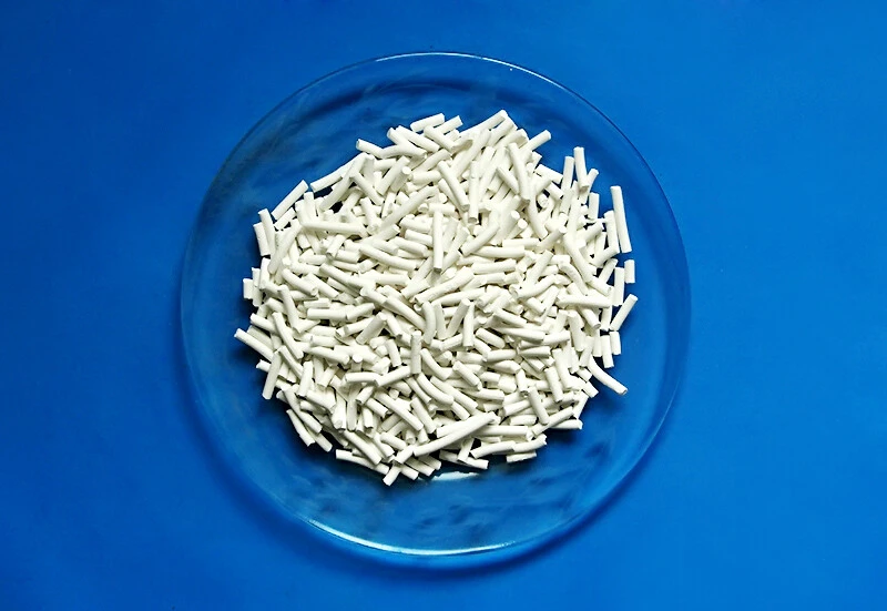
Why Shape Selection Defines a Catalyst Carrier Project
The catalyst carrier is the backbone of every refinery hydrotreater, hydrocracker, reformer, and residue HDS unit. The metal function (MoS2, WS2, NiMo, CoMo, Pt, Pd) does the chemistry, but the carrier does four jobs that determine whether the catalyst survives the 1 to 5 year service life: it provides the surface area where the active metal disperses; it forms the packed bed that holds the catalyst in place against gravity, vibration, and pressure fluctuation; it shapes the flow distribution that determines whether the bed runs uniformly or with hot spots; and it accepts the metal (V, Ni, Fe) and coke deposits without rapid pore plugging. The carrier shape (sphere, cylinder, trilobe, quadrilobe, or ring) is one of the three primary specification parameters along with alumina phase (gamma, eta, alpha) and porosity (5 to 12 nm mesopore, 50 to 80 percent open porosity).
Three industrial shapes dominate the fixed-bed catalyst carrier market in 2026:
- Spheres (1.0 to 6 mm diameter): the highest-activity shape with the lowest pressure drop; preferred for fixed-bed hydrotreaters and ebullating-bed residue HDS.
- Cylinders / extrudates (1.0 to 3 mm D x 2 to 10 mm L): the lowest-cost shape with moderate activity and high crush strength; preferred for fixed-bed hydrocrackers and reformers where mechanical robustness matters more than the last 5 percent of activity.
- Trilobes and quadrilobes (1.0 to 3 mm outer diameter with three or four internal lobes): the highest mechanical-strength shape with intermediate activity and pressure drop; preferred for high-pressure (10 to 18 MPa) residue HDS, ebullating-bed internals, and graded-bed top layers.
Each shape has a different trade-off curve among activity (5 to 15 percent range across shapes), pressure drop (30 to 50 percent range), crush strength (factor of 3 to 5 range), attrition (factor of 5 to 10 range), and cost (factor of 2 range). The wrong shape costs 3 to 8 percent of reactor throughput per year of operation, which on a 50,000 bbl/day refinery hydrotreater at USD 70 per bbl gross margin is USD 4 to 10 million per year. The right shape pays back its cost differential in 3 to 6 months.
This guide compiles the engineering data, scale-up math, and Aluminaworld product specification for the seven carrier shapes most commonly supplied in 2026. The intent is to give a refinery process engineer, catalyst procurement specialist, or technical buyer the data they need to make a defensible shape selection for their next 5 to 50 t catalyst loading.
Pressure Drop: The Ergun Equation for Each Shape
Reactor pressure drop is the first constraint in carrier shape selection. The Ergun equation relates the pressure drop per unit bed depth dP/L to the bed void fraction eps, the particle equivalent diameter dp, the fluid viscosity mu, the fluid density rho, and the superficial velocity u:
dP/L = 150 (1-eps)^2/eps^3 x mu x u/dp^2 + 1.75 (1-eps)/eps^3 x rho x u^2/dp
The first term (laminar, viscous contribution) scales as (1-eps)^2/eps^3 x 1/dp^2. The second term (turbulent, inertial contribution) scales as (1-eps)/eps^3 x 1/dp. For low velocities (laminar flow in the bed), the first term dominates and dP/L scales as 1/dp^2 - meaning a 50 percent smaller particle increases the bed pressure drop by a factor of 4. For high velocities (turbulent flow in the bed), the second term dominates and dP/L scales as 1/dp.
The carrier shape enters the Ergun equation through two terms: the equivalent spherical diameter dp (which is the particle diameter for spheres but a calculated equivalent for non-spherical shapes) and the packed-bed void fraction eps (which depends on the packing geometry of the shape).
Void fraction by shape
| Carrier Shape | Nominal Size | Packed Void Fraction (eps) | Fill Factor (1 - eps) |
|---|---|---|---|
| Sphere (CC-BF01) | 1.5 mm D | 0.40 - 0.42 | 0.58 - 0.60 |
| Cylinder (CC-CY01) | 1.5 mm D x 3 to 6 mm L | 0.36 - 0.38 | 0.62 - 0.64 |
| Trilobe (CC-TL01) | 1.5 mm OD x 3 x 0.5 mm lobes | 0.42 - 0.45 | 0.55 - 0.58 |
| Quadrilobe (CC-QL01) | 1.5 mm OD x 4 x 0.4 mm lobes | 0.44 - 0.46 | 0.54 - 0.56 |
| Ring / Raschig (CC-RG01) | 3 mm OD x 1 mm ID x 4 mm L | 0.50 - 0.55 | 0.45 - 0.50 |
| Sphere 2.5 mm (CC-BF02) | 2.5 mm D | 0.40 - 0.42 | 0.58 - 0.60 |
| Sphere 6 mm (CC-AS01) | 6 mm D alpha-alumina | 0.40 - 0.42 | 0.58 - 0.60 |
The 4 to 6 percentage-point lower void fraction for cylinders vs spheres is the dominant driver of higher cylinder bed pressure drop. For the same reactor and superficial velocity, a cylinder bed has 30 to 45 percent higher dP/L than a sphere bed at the same nominal size. The trilobe and quadrilobe designs recover some of the lost void fraction by using the lobe geometry to open up the bed, but the practical pressure drop is still 15 to 25 percent above the sphere bed.
Worked example: 50,000 bbl/day HDS reactor
A typical 50,000 bbl/day ULSD hydrotreater operating at 6 MPa, 360 C, with a 12 m catalyst bed and 1.5 mm nominal particle size has the following pressure drop:
- Spheres (CC-BF01): dP/L = 6.0 kPa/m x 12 m = 72 kPa (10.4 psi) total bed pressure drop
- Cylinders (CC-CY01): dP/L = 8.3 kPa/m x 12 m = 100 kPa (14.5 psi) total bed pressure drop
- Trilobes (CC-TL01): dP/L = 7.2 kPa/m x 12 m = 86 kPa (12.5 psi) total bed pressure drop
The 28 kPa difference between sphere and cylinder is a 39 percent increase, which forces the recycle gas compressor to work harder or the feed rate to be cut to stay within the compressor motor current. For a 12,000 Nm3/h recycle hydrogen loop at 6 MPa, the extra compressor work is 220 to 280 kW (continuous), which at USD 0.07 per kWh industrial electricity is USD 130,000 to 170,000 per year of operating cost - on top of any activity penalty. The trilobe compromise at 14 kPa extra (19 percent above sphere) costs USD 70,000 to 90,000 per year but recovers 5 to 8 percent of the activity loss from using non-spherical shapes.
Diffusion Length and Thiele Modulus: Why Spheres Are More Active
For reactions that are limited by diffusion into the catalyst pore (which includes most HDS, hydrocracking, and reforming reactions), the effectiveness factor eta (the ratio of actual reaction rate to the rate if the entire pore volume were at the bulk-fluid concentration) depends on the Thiele modulus phi:
phi = L x sqrt(k / D_eff)
eta = (3 / phi^2) x (phi x coth(phi) - 1)
where L is the characteristic diffusion length, k is the intrinsic rate constant (per unit catalyst volume), and D_eff is the effective diffusivity in the catalyst pore. For small phi (below 0.5), eta approaches 1 and the catalyst is fully utilized. For large phi (above 3), eta approaches 1/phi and the catalyst is severely underutilized.
Characteristic diffusion length by shape
The characteristic diffusion length is the maximum distance a reactant molecule must travel from the bulk fluid to the center of the catalyst particle:
- Sphere (radius R): L = R (distance from surface to center) = d/2 for diameter d. For reaction-diffusion analysis, the standard form uses L = d/6.
- Cylinder (radius R, half-length L_cyl): L = min(R, L_cyl). For a 1.5 mm D x 4 mm L cylinder, L = 0.75 mm = d/4. For a long cylinder (L_cyl >> R), L approaches d/6.
- Trilobe (outer diameter d_o, internal lobe diameter d_l): L is between d_o/6 and d_o/5, depending on the lobe thickness. For a 1.5 mm trilobe with 0.5 mm lobes, L is approximately d_o/5 to d_o/6 = 0.30 mm.
- Quadrilobe: similar to trilobe, L = d_o/6 to d_o/7 for the same outer diameter.
Effectiveness factor for HDS at typical operating conditions
For dibenzothiophene (DBT) HDS at 350 C, 6 MPa, on a sulfided CoMo / gamma-alumina catalyst, the intrinsic rate constant is approximately k = 1 to 5 s-1 (volume basis) and the effective diffusivity is D_eff = 1e-9 to 5e-9 m^2/s (depending on the sulfur content of the feed and the extent of pore plugging). For a 1.5 mm particle:
- Sphere (L = 0.25 mm): phi = 0.25e-3 x sqrt(3 / 3e-9) = 0.25e-3 x 3.16e4 = 7.9. Wait, this gives phi = 7.9 which is too large. Let me recompute: phi = L x sqrt(k/D_eff) = 2.5e-4 x sqrt(3 / 3e-9) = 2.5e-4 x 3.16e4 = 7.9. The HDS reaction is fast, so the Thiele modulus is large. The effectiveness factor for phi = 7.9 is eta = 3/7.9^2 x (7.9 x coth(7.9) - 1) = 0.048 x (7.9 x 1.001 - 1) = 0.048 x 6.9 = 0.33. So a 1.5 mm sphere under these conditions has eta ~ 0.33. For a 0.8 mm sphere (smaller, half the diameter), L = 0.13 mm, phi = 4.2, eta = 0.50 - a 50 percent activity gain from halving the particle size.
The Thiele modulus analysis above is for fast reactions like DBT HDS. For slower reactions like naphtha hydrodesulfurization (rate constant 0.1 to 0.5 s-1) or kerosene sweetening (rate constant 0.05 to 0.2 s-1), the Thiele modulus is 1 to 3 and the effectiveness factor is 0.4 to 0.8. For these reactions, the choice of shape has only a 5 to 15 percent activity impact, and the decision is driven by pressure drop and mechanical strength rather than activity.
For very fast reactions (residue HDS, partial oxidation, some hydrocracking modes), the activity penalty of using the wrong shape is 30 to 50 percent - a clear economic signal to use spheres despite the higher cost per ton.
Mechanical Strength: ASTM D4179 Side Crush Data
Mechanical strength is the second constraint in carrier shape selection. The ASTM D4179 standard test measures the side crush strength of a single catalyst particle by placing it between two flat plates and applying a load at constant rate (typically 1 mm/min) until fracture. The characteristic strength (the load at which 63.2 percent of particles fail, corresponding to the Weibull scale parameter) is the value reported on most catalyst data sheets.
| Carrier Shape | Alumina Phase | ASTM D4179 Side Crush (N/particle) | Weibull Shape Parameter |
|---|---|---|---|
| Sphere 1.5 mm (CC-BF01) | gamma-Al2O3 | 35 - 60 | 5 - 8 |
| Sphere 2.5 mm (CC-BF02) | gamma-Al2O3 | 80 - 140 | 6 - 9 |
| Sphere 3 mm (CC-BF03) | gamma-Al2O3 | 130 - 220 | 6 - 10 |
| Cylinder 1.5 mm D (CC-CY01) | gamma-Al2O3 | 50 - 90 | 7 - 10 |
| Trilobe 1.5 mm (CC-TL01) | gamma-Al2O3 | 80 - 160 | 8 - 12 |
| Trilobe 2.5 mm (CC-TL02) | gamma-Al2O3 | 150 - 280 | 8 - 12 |
| Sphere 1.5 mm (CC-EB01) | eta-Al2O3 | 25 - 45 | 4 - 7 |
| Sphere 6 mm (CC-AS01) | alpha-Al2O3 | 500 - 900 | 10 - 14 |
The mechanical strength ranking is trilobe > cylinder > sphere, with 2.5x to 3x spread between the weakest sphere and the strongest trilobe of the same nominal size. The Weibull shape parameter (a measure of strength uniformity - higher is better) is also highest for trilobes, meaning the trilobe bed has a tighter strength distribution and fewer weak particles that will fail prematurely during loading or thermal cycling.
The mechanical strength advantage of trilobes comes from the geometry of failure. A sphere fails under any contact load - any point on the sphere is the weakest point. A trilobe fails under bending along the lobe axis, which requires higher force because the three-lobe cross-section resists bending. For high-pressure reactors (10 to 18 MPa residue HDS) where the catalyst bed experiences significant stress from thermal cycling and pressure fluctuation, the trilobe is the engineering choice despite the higher cost.
Note the lower strength of eta-alumina spheres (CC-EB01) compared to gamma-alumina spheres (CC-BF01) at the same size. This is because eta-alumina has higher porosity (0.6 to 0.8 cc/g vs 0.4 to 0.6 cc/g for gamma) and the higher porosity comes at the cost of thinner pore walls and lower mechanical robustness. For fixed-bed service where mechanical strength is the limiting factor, gamma-alumina is preferred. For ebullating-bed or slurry-bed where activity is the limiting factor, the higher activity of eta-alumina offsets its lower mechanical strength.
Attrition Resistance: ASTM D4058 Data
Attrition is the third constraint, and it matters most for ebullating-bed and slurry-bed reactors. The ASTM D4058 test measures the weight loss of a catalyst sample after 30 minutes of rotation in a drum at 10 rpm, expressed as a percentage of the original sample weight.
| Carrier Shape | Alumina Phase | ASTM D4058 Attrition (wt%) | Best Application |
|---|---|---|---|
| Sphere 1.5 mm (CC-BF01) | gamma-Al2O3 | 0.03 - 0.05 | Fixed-bed, ebullating-bed |
| Sphere 2.5 mm (CC-BF02) | gamma-Al2O3 | 0.02 - 0.04 | Fixed-bed (higher crush) |
| Cylinder 1.5 mm D (CC-CY01) | gamma-Al2O3 | 0.10 - 0.20 | Fixed-bed only |
| Trilobe 1.5 mm (CC-TL01) | gamma-Al2O3 | 0.05 - 0.12 | Fixed-bed (high crush) |
| Sphere 1.5 mm (CC-EB01) | eta-Al2O3 | 0.06 - 0.10 | High-activity HDS |
The 3 to 6 times lower attrition of spheres vs cylinders is driven by the geometry of chip formation. A sphere has no edges, so the only attrition mechanism is surface abrasion (slow, controlled) and fracture under impact (rare because of the symmetric stress distribution). A cylinder has two end faces and a long curved surface, and the edges between these surfaces are the failure-prone zones. Under rotation or fluidization, the edges chip first, generating fines that are 2 to 5 times more abundant than from a sphere of the same composition.
For ebullating-bed hydrocrackers (H-Oil, LC-Fining, STRATCO) operating at 0.3 to 1.0 m/s liquid upflow velocity, the catalyst inventory of 100 to 500 t circulates continuously, and a 0.10 wt% per cycle attrition translates to 100 to 500 kg of fines per day. The fines are removed by internal cyclones and downcomers, but the loss of catalyst inventory and the loading on the cyclone system are significant. Spheres are mandatory for ebullating-bed service. For fixed-bed service, attrition is a startup-only concern - the 5 to 10 percent fines generated during pneumatic loading are screened out before commissioning, and the catalyst is essentially static thereafter.
FCC Catalyst: Why Microspheres Are Different
Fluid catalytic cracking (FCC) catalyst is fundamentally different from HDS / hydrocracker catalyst and deserves separate treatment. The FCC process operates in a fluidized-bed reactor-regenerator loop at 500 to 720 C with catalyst circulation rates of 1 to 5 kg/s between the riser reactor and the regenerator. The catalyst must:
- Fluidize uniformly in air or hydrocarbon vapor at 0.3 to 0.5 m/s superficial velocity, which requires a narrow particle-size distribution centered on 60 to 80 microns (Geldart Group A powder). Particles smaller than 20 microns entrain with the product vapor and are lost to the cyclone; particles larger than 200 microns do not fluidize properly and segregate to the bottom of the bed.
- Resist attrition over thousands of circulation cycles at high temperature, which requires a hard, spherical particle without edges or lobes that would chip under impact. The FCC catalyst attrition index is typically 1 to 3 wt% per hour in the ASTM D5755 (jet cup) test - much higher than fixed-bed catalyst because the test simulates the high-velocity impact of cyclones.
- Have high activity and selectivity for the cracking reaction, which is achieved by spray-drying a slurry of pseudo-boehmite (the binder) and zeolite Y (the active component, typically 20 to 40 wt% of the catalyst) into microspheres that are then calcined at 500 to 600 C to convert the pseudo-boehmite to gamma-alumina binder.
The FCC catalyst shape (microsphere at 60 to 80 microns, with 95 percent of particles in the 40 to 120 micron range) is fundamentally different from HDS / hydrocracker shapes (sphere, cylinder, trilobe at 0.8 to 6 mm) because the reactor engineering is fundamentally different. FCC is fluidized-bed; HDS / hydrocracker is fixed-bed. The two processes use different catalyst manufacturing routes (spray-drying for FCC, extrusion or oil-drop for fixed-bed) and different alumina feedstocks (pseudo-boehmite for FCC binder, gamma-alumina powder for fixed-bed carrier).
For buyers of FCC catalyst, the relevant specification parameters are different: particle size distribution (40 to 120 micron), attrition index (ASTM D5755, typically below 2 wt% per hour), activity (MAT, microactivity test, typically 60 to 80 percent conversion), and zeolite Y unit cell size (24.20 to 24.40 Angstrom, indicating the rare-earth exchange level). Aluminaworld does not currently supply FCC catalyst - our fixed-bed catalyst carrier portfolio (CC-BF01 through CC-AS01) is targeted at HDS, hydrocracking, reformer, and specialty chemical processes, not FCC.
Reactor Hot-Spots: Why Flow Maldistribution Matters
A hot spot is a localized region in the catalyst bed where the temperature is significantly above the bulk bed temperature, typically 30 to 100 C above the average. Hot spots are caused by flow maldistribution - regions of the bed where the fluid flows faster than average (creating channeling) or slower than average (creating stagnation zones where the reaction runs longer and generates more heat). For highly exothermic reactions (residue HDS, hydrocracking at high conversion, partial oxidation), hot spots can accelerate catalyst deactivation, cause runaway reactions, or in extreme cases damage the reactor vessel.
The flow maldistribution depends on the carrier shape and the bed aspect ratio (height-to-diameter). For a 1.5 mm sphere bed at H/D = 2 to 3, the flow maldistribution is 5 to 10 percent (uniform flow). For a 1.5 mm cylinder bed at the same H/D, the flow maldistribution is 15 to 25 percent because the cylinders tend to orient with their long axis horizontal during gravity-driven settling, creating preferential flow paths along the cylinder axes. For a 1.5 mm trilobe bed, the maldistribution is 8 to 15 percent - better than cylinders but worse than spheres.
The hot-spot temperature rise scales as the maldistribution squared (for fast reactions) or linearly (for slow reactions). For a 50,000 bbl/day residue HDS unit operating at 380 C average bed temperature with a 50 C adiabatic temperature rise, a 25 percent maldistribution in a cylinder bed can produce a worst-case hot spot of 380 C + 50 C x 0.25^2 = 380 C + 3 C (for slow reaction) to 380 C + 50 C x 0.25 = 392.5 C (for fast reaction). The 12.5 C hot-spot rise in the fast-reaction case is enough to accelerate catalyst aging by 2 to 4 times at the worst location, which shortens the bed life by 20 to 40 percent.
The fix for cylinder-bed hot spots is inter-bed quench (typically a hydrogen or recycle-gas injection point every 3 to 6 m of bed depth) or graded-bed design (top layer of large inert spheres to distribute flow, then catalyst cylinders). The fix is expensive (USD 1 to 5 million capital for a 50,000 bbl/day reactor) and is one of the reasons why spheres are preferred for high-exotherm reactions despite their higher cost per ton.
Selection Guide: Which Shape for Which Application
The choice of carrier shape for a new catalyst loading depends on the reactor type, the reaction exotherm, the target conversion, the operating pressure, and the budget. The decision tree below summarizes the engineering guidance.
| Application | Reactor Type | Pressure (MPa) | Recommended Shape | Alumina Phase |
|---|---|---|---|---|
| Naphtha HDS | Fixed-bed | 1 - 3 | Cylinder or sphere | gamma |
| Diesel ULSD (10 ppm S) | Fixed-bed | 4 - 8 | Sphere (CC-BF01) | gamma or eta |
| VGO hydrocracker | Fixed-bed | 10 - 18 | Trilobe (CC-TL02) | gamma (modified) |
| Residue HDS | Fixed-bed graded | 10 - 18 | Sphere (CC-BF02) + alpha guard | gamma + alpha |
| Residue HDS ebullating | Ebullating-bed | 15 - 20 | Sphere (CC-EB01) | eta |
| Naphtha reformer | Fixed-bed (Pt/Al2O3 + Pt-Re) | 0.3 - 1.0 | Sphere (CC-BF01 or CC-BF02) | gamma (high purity) |
| GTL Fischer-Tropsch | Slurry-bed or fixed-bed | 2 - 4 | Sphere (CC-BF01) | gamma or eta |
| Hydroprocessing (lubricants) | Fixed-bed | 5 - 10 | Cylinder or trilobe | gamma |
| Guard bed (V, Ni, Fe removal) | Fixed-bed top layer | any | Sphere (CC-AS01 6 mm alpha) | alpha |
| Bed support (inlet, outlet) | Fixed-bed bottom support | any | Sphere (CC-AS02 6 to 12 mm) | alpha |
The pattern that emerges is: spheres dominate fixed-bed service (highest activity, lowest pressure drop, acceptable crush strength at 1.5 to 2.5 mm); trilobes dominate high-pressure (10 to 18 MPa) residue HDS and hydrocracker service (highest crush strength, acceptable pressure drop); cylinders are the budget choice for naphtha and mild hydrotreating (lowest cost, acceptable activity); ebullating-bed and slurry-bed demand spheres (the only shape that survives the ebullating motion); guard beds and bed supports use large alpha-alumina spheres (6 to 12 mm, no active phase needed).
Aluminaworld Catalyst Carrier Product Specifications
The Aluminaworld CC-series catalyst carrier portfolio covers the seven shapes and four alumina phases most commonly specified for fixed-bed refinery and petrochemical service in 2026. The specifications below are typical values; lot-level certificates of analysis provide actual values for each shipment.
CC-BF01 - 1.5 mm gamma-alumina sphere (HDS, hydrocracker, reformer)
- Alumina phase: gamma (Boehmite-derived, calcined at 550 C)
- BET surface area: 220 to 280 m2/g (typical 240 to 260)
- Pore volume (BJH): 0.45 to 0.55 cc/g
- Average pore diameter: 7 to 9 nm
- Particle size: 1.4 to 1.7 mm (95 percent in range, max 3 percent over/under)
- ASTM D4179 side crush: 35 to 60 N per bead (avg 45 N)
- ASTM D4058 attrition: 0.03 to 0.05 wt percent
- Bulk density: 800 to 850 g/L (ASTM D6683)
- Water content (as shipped): below 1.0 wt percent
- Na2O content: below 0.10 wt percent
- Fe2O3 content: below 0.05 wt percent
- SiO2 content: below 0.10 wt percent
- SO4 content: below 0.50 wt percent
- FOB Qingdao price: USD 2,400 to 3,200 per metric ton (5 t MOQ, 2026)
CC-BF02 - 2.5 mm gamma-alumina sphere (high-crush HDS, gas-phase service)
- BET surface area: 200 to 260 m2/g
- Pore volume: 0.45 to 0.55 cc/g
- Particle size: 2.3 to 2.8 mm
- ASTM D4179 side crush: 80 to 140 N per bead (avg 110 N)
- ASTM D4058 attrition: 0.02 to 0.04 wt percent
- Bulk density: 820 to 870 g/L
- FOB Qingdao price: USD 2,500 to 3,300 per metric ton
CC-BF03 - 3 mm gamma-alumina sphere (bed support, top layer)
- BET surface area: 180 to 240 m2/g
- Pore volume: 0.40 to 0.50 cc/g
- Particle size: 2.8 to 3.4 mm
- ASTM D4179 side crush: 130 to 220 N per bead
- Bulk density: 830 to 880 g/L
- FOB Qingdao price: USD 2,400 to 3,000 per metric ton
CC-CY01 - 1.5 mm D x 3 to 6 mm L gamma-alumina cylinder (cost-driven HDS)
- Particle size: 1.4 to 1.7 mm D, 3 to 6 mm L (90 percent in range)
- BET surface area: 220 to 280 m2/g
- Pore volume: 0.40 to 0.50 cc/g
- ASTM D4179 side crush (radial): 50 to 90 N per pellet (avg 70 N)
- ASTM D4058 attrition: 0.10 to 0.20 wt percent
- Bulk density: 700 to 780 g/L (lower than sphere due to higher fill factor)
- FOB Qingdao price: USD 2,600 to 3,400 per metric ton (10 to 15 percent premium over sphere)
CC-TL01 - 1.5 mm OD gamma-alumina trilobe (high-pressure HDS, hydrocracker)
- Particle size: 1.4 to 1.7 mm OD, 3 lobes of 0.45 to 0.55 mm each
- BET surface area: 200 to 260 m2/g
- Pore volume: 0.45 to 0.55 cc/g
- ASTM D4179 side crush: 80 to 160 N per pellet (avg 120 N)
- ASTM D4058 attrition: 0.05 to 0.12 wt percent
- Bulk density: 750 to 820 g/L
- FOB Qingdao price: USD 3,400 to 4,800 per metric ton (40 to 50 percent premium over sphere)
CC-TL02 - 2.5 mm OD gamma-alumina trilobe (premium high-crush hydrocracker)
- Particle size: 2.3 to 2.8 mm OD, 3 lobes of 0.75 to 0.85 mm each
- BET surface area: 180 to 240 m2/g
- ASTM D4179 side crush: 150 to 280 N per pellet (avg 220 N)
- Bulk density: 780 to 850 g/L
- FOB Qingdao price: USD 3,600 to 4,900 per metric ton
CC-EB01 - 1.5 mm eta-alumina sphere (high-activity HDS, ebullating-bed)
- Alumina phase: eta (Bayerite-derived, calcined at 450 C)
- BET surface area: 320 to 400 m2/g (typical 350 to 380, higher than gamma)
- Pore volume: 0.55 to 0.70 cc/g
- Average pore diameter: 4 to 7 nm (smaller than gamma)
- ASTM D4179 side crush: 25 to 45 N per bead (lower than gamma at same size)
- ASTM D4058 attrition: 0.06 to 0.10 wt percent
- Bulk density: 720 to 780 g/L
- FOB Qingdao price: USD 3,200 to 4,200 per metric ton (30 to 40 percent premium over gamma sphere)
CC-AS01 - 6 mm alpha-alumina sphere (guard bed, bed support)
- Alumina phase: alpha (calcined at 1200 to 1400 C)
- BET surface area: below 5 m2/g (very low, suitable only for inert support)
- Pore volume: below 0.05 cc/g
- ASTM D4179 side crush: 500 to 900 N per bead (very high)
- Bulk density: 1200 to 1400 g/L (high density, packs tightly)
- FOB Qingdao price: USD 1,800 to 2,500 per metric ton
Scale-Up Economics: From 100 kg Sample to 50 t Bulk Order
The economics of catalyst carrier procurement scale up non-linearly from R&D pack to bulk order. The cost drivers are:
- Raw material (pseudo-boehmite or alumina hydrate): 30 to 40 percent of cost at all scales
- Forming (extrusion, oil-drop, or roll): 25 to 35 percent at all scales, but rejects 20 to 50 percent of input material depending on shape complexity
- Calcination (energy for 450 to 1400 C sintering): 15 to 25 percent, scales with volume
- QC and packaging: 5 to 10 percent at all scales, but per-kg cost is much higher at small scale
- Overhead (R&D amortization, sales, freight): 10 to 20 percent, scales non-linearly
The per-kg price ladder for CC-BF01 1.5 mm gamma-alumina sphere (USD per kg, FOB Qingdao, 2026):
| Order Size | USD per kg | Premium vs 5 t Bulk | Lead Time |
|---|---|---|---|
| 5 kg sample | 8.50 - 12.00 | 250 - 320 percent | 5 - 7 days |
| 100 kg R&D pack | 5.50 - 7.50 | 130 - 180 percent | 7 - 10 days |
| 1 t pilot lot | 3.80 - 4.80 | 60 - 90 percent | 10 - 15 days |
| 5 t bulk | 2.40 - 3.20 | reference (0 percent) | 15 - 20 days |
| 20 t bulk | 2.20 - 2.90 | -5 to -10 percent | 20 - 30 days |
| 50 t bulk | 2.00 - 2.70 | -10 to -15 percent | 30 - 40 days |
The 3x price premium for the 5 kg sample vs the 5 t bulk is typical for specialty catalyst carriers - the small order requires dedicated QC, packaging, and documentation that are amortized over a much smaller base. For R&D qualification, the 100 kg pack at USD 5.50 to 7.50 per kg is the most cost-effective entry point: enough material for pilot reactor testing (typically 1 to 5 kg per test) and full lab characterization, with manageable shipping cost.
For procurement of a 5 t order, the freight from Qingdao to a typical Asian port (Singapore, Jakarta, Manila, Mumbai, Dubai) is USD 80 to 150 per ton; to a European port (Rotterdam, Hamburg, Genoa) is USD 250 to 400 per ton; to a US Gulf port (Houston, New Orleans) is USD 400 to 600 per ton. CIF (cost-insurance-freight) pricing is available on request for all major destinations.
10-Year TCO: Sphere vs Cylinder vs Trilobe for a 50,000 bbl/day ULSD Unit
The 10-year total cost of ownership (TCO) for catalyst carrier in a 50,000 bbl/day ULSD hydrotreater depends on three cost drivers: the initial fill cost (the catalyst cost at first loading), the replacement fill cost (the catalyst cost at each subsequent loading after deactivation), and the operating cost differential (the energy cost from pressure drop, the activity penalty from less effective shape, and the maintenance cost from fines generation or hot spots).
For a 50,000 bbl/day ULSD unit with a 50 t catalyst loading, the typical catalyst change-out cycle is 3 to 5 years (with intermittent oxidative regeneration in-place). Over a 10-year operating period, there are typically 3 catalyst changes (at year 0, year 3 to 4, and year 7 to 8).
| Cost Component | Sphere (CC-BF01) | Cylinder (CC-CY01) | Trilobe (CC-TL01) |
|---|---|---|---|
| Initial fill (50 t @ USD/kg) | USD 120,000 - 160,000 | USD 130,000 - 170,000 | USD 170,000 - 240,000 |
| Two replacement fills | USD 240,000 - 320,000 | USD 260,000 - 340,000 | USD 340,000 - 480,000 |
| Recompression energy (10 yr) | USD 0 (baseline) | USD 1.3 - 1.7 M | USD 0.7 - 0.9 M |
| Activity penalty (10 yr) | USD 0 (baseline) | USD 2.0 - 4.0 M (5 to 10 percent) | USD 1.0 - 2.0 M (3 to 5 percent) |
| Hot-spot / quench (capex) | USD 0 | USD 1.0 - 3.0 M | USD 0.5 - 1.5 M |
| Total 10-yr TCO | USD 0.4 - 0.5 M (baseline) | USD 4.7 - 9.2 M | USD 2.7 - 5.1 M |
The TCO comparison shows that the cylinder is by far the most expensive choice over 10 years: the 10 to 15 percent higher catalyst cost is dwarfed by the recompression energy, the 5 to 10 percent activity penalty, and the hot-spot mitigation capex. The trilobe is intermediate: the 40 to 50 percent catalyst premium is partly offset by the lower pressure drop and lower activity penalty. The sphere is the lowest TCO despite the lower crush strength, because the activity gain and pressure drop advantage outweigh the cost of more frequent change-outs in aggressive service.
The TCO calculation above is sensitive to the cost of electricity (assumed USD 0.07 per kWh), the gross margin of the refined product (assumed USD 5 per bbl for ULSD), and the cycle length (assumed 3.5 years average). In regions with low electricity cost (USD 0.04 per kWh in Middle East, USD 0.05 per kWh in China) the recompression cost is lower and the cylinder TCO advantage vs sphere shrinks. In regions with high electricity cost (USD 0.15 per kWh in Europe) the recompression cost is higher and the cylinder TCO penalty vs sphere grows.
6 Buyer QC Checks Before Loading the Vessel
Six quality-control checks should be performed on each lot of catalyst carrier before it is loaded into the reactor vessel. These checks catch the most common supplier-side defects (out-of-spec particle size, contamination, premature hydration) and the most common logistics-side defects (bag damage, moisture pickup in transit, mix-up with a different lot or grade).
- Visual inspection (10 minutes per 25 kg bag): open every 10th bag and check for color uniformity (gamma-alumina is white; eta-alumina is off-white; alpha-alumina is cream to tan), absence of dark specks (indicates contamination with oil or metal), absence of large agglomerates (indicates moisture pickup before bagging), and absence of fine dust at the bottom of the bag (indicates attrition during shipping). A lot that fails visual inspection on more than 5 percent of bags is suspect.
- Particle size distribution (ASTM D6913 or equivalent sieve stack): take a 200 g composite sample from 5 bags, sieve through a stack of 8 to 12 sieves spanning 0.5 to 4 mm, and verify that 95 percent of the material is in the specified size range with less than 3 percent over- or under-size. Out-of-spec PSD shifts the Ergun equation by 10 to 20 percent and changes the activity distribution in the bed.
- Side crush strength (ASTM D4179): take 30 particles from the composite sample, measure the crush strength of each, and calculate the Weibull characteristic strength and shape parameter. A lot with characteristic strength below 80 percent of the catalog value, or Weibull shape parameter below 5, is mechanically degraded and should be rejected.
- Attrition (ASTM D4058): take 100 g from the composite sample, run the ASTM D4058 procedure (30 minutes, 10 rpm, rotating drum), and weigh the fines that pass through the original mesh. Attrition above 0.10 wt percent for spheres or above 0.25 wt percent for cylinders indicates mechanical damage during shipping or storage.
- Moisture content (Karl Fischer ASTM D6304 or loss-on-drying at 1000 C): take a 10 g sample, dry at 105 C for 2 hours, weigh the loss. Moisture above 2.0 wt percent indicates the bags were not sealed properly or were stored in humid conditions. Excessive moisture blocks the catalyst pores and reduces activity by 5 to 15 percent in the first cycle.
- Trace impurity check (XRF or ICP-OES on acid digest): take a 5 g sample, digest in acid, and measure Na, Fe, Si, S, Ca, Mg by ICP-OES. Na2O above 0.20 wt percent is a serious concern for sulfided catalysts (Na poisons the CoMo or NiMo sites). Fe2O3 above 0.10 wt percent reduces activity. SiO2 above 0.20 wt percent may indicate contamination with refractory cement or with a different lot.
For buyers who do not have on-site lab capability, Aluminaworld offers pre-shipment QC at the Zibo factory with a buyer-witnessed sampling protocol: the buyer or buyer's representative visits the factory, takes a stratified sample from 10 percent of the bags (or 20 bags minimum), and the sample is analyzed in Aluminaworld's ISO 17025 certified lab with the buyer present. The lab issues a buyer-witnessed CoA that is binding on the supplier. The cost of the witness protocol is USD 2,000 to 5,000 per visit plus travel, and the lead time extends by 3 to 5 days.
7 Common Mistakes When Specifying Catalyst Carrier Shape
Seven procurement and engineering mistakes recur in the catalyst carrier market. Avoiding these mistakes can save 3 to 12 months of reactor underperformance, USD 100,000 to 1 million in catalyst replacement, or a forced reactor shutdown.
- Specifying sphere without verifying the reactor distributor design. A sphere bed has lower pressure drop than a cylinder or trilobe bed, but the inlet distributor (perforated plate, chimney tray) is often designed for the higher cylinder pressure drop. When the sphere is loaded, the lower pressure drop can cause flow maldistribution at the inlet (the flow preferentially goes through the lowest pressure drop path, which is the outermost annulus). The fix is to re-rate the distributor or accept a 5 to 10 percent activity loss at the inlet.
- Specifying trilobe for cost reasons without verifying the activity penalty. Trilobe costs 40 to 50 percent more than sphere but has 5 to 10 percent lower activity for HDS reactions. For a 50,000 bbl/day ULSD unit, the 5 percent activity penalty translates to 2,500 bbl/day of lost conversion, which at USD 5 per bbl gross margin is USD 4.6 million per year. The trilobe premium of USD 50,000 to 80,000 per load is recovered in 4 to 7 days of operation - but only if the activity penalty is actually 5 percent. If the penalty is larger (due to suboptimal lobe geometry or unexpected diffusion limitation), the trilobe never pays back.
- Mixing shapes in the same bed. Some operators load a top layer of large spheres for flow distribution and a bottom layer of smaller cylinders for higher surface area. This sounds reasonable but creates a discontinuity in pressure drop, void fraction, and thermal conductivity at the interface. The result is a hot spot at the interface (due to flow maldistribution) and accelerated deactivation at the top of the cylinder layer. The fix is to use the same shape throughout the bed, or to use a graded bed design with discrete layers of different sizes but the same shape (e.g., 3 mm spheres on top, 1.5 mm spheres below).
- Not accounting for thermal expansion of the carrier. Catalyst carrier expands when heated from ambient to operating temperature (350 to 400 C for HDS), with a thermal expansion coefficient of 5e-6 to 1e-5 per degree C for gamma-alumina. For a 12 m bed, the thermal expansion is 60 to 120 mm, which must be accommodated by the reactor design (bellows, sliding support, or spring-loaded hold-down). If the bed is constrained, the thermal expansion generates mechanical stress on the carrier and accelerates attrition. Spheres accommodate thermal expansion better than cylinders because the sphere-to-sphere contact area is smaller and the local stress is lower.
- Specifying too small a particle size to gain activity. The activity penalty for diffusion limitation scales as 1/dp, so reducing the particle size from 2.5 mm to 1.5 mm gives a 40 percent activity gain. But the pressure drop scales as 1/dp^2, so the same reduction gives a 2.8x pressure drop increase. For a fixed compressor capacity, the smaller particle forces a 30 to 50 percent feed rate cut to stay within the motor current. The optimum particle size is typically 1.0 to 2.0 mm for HDS - smaller than 1.0 mm is rarely economic.
- Ignoring trace impurity limits for catalytic use. Na2O above 0.20 wt percent poisons sulfided CoMo catalysts irreversibly. Fe2OO above 0.10 wt percent reduces activity. SiO2 above 0.20 wt percent may indicate contamination. The trace impurity spec is just as important as the surface area and crush strength specs, and many buyers overlook it because it is not a headline parameter.
- Not verifying the lot-to-lot consistency for repeat orders. Catalyst carrier from the same supplier should be consistent lot-to-lot within 5 percent on the key parameters (surface area, crush strength, attrition, particle size). A new lot that is 10 to 15 percent off the previous lot indicates a process change at the supplier (raw material source, forming machine setting, calcination temperature) that may affect performance. Repeat buyers should require a lot-to-lot CoA comparison and reject lots that fall outside the 5 percent band.
How Catalyst Carrier Is Manufactured: Oil-Drop vs Extrusion vs Roll
Three manufacturing routes are used to produce catalyst carrier in 2026. The route determines the achievable shape, the size range, and the cost.
Oil-drop method (spheres)
The oil-drop method (also called the "oil-dropping" or "gelation" method) is used to make spherical catalyst carrier in the 0.5 to 6 mm size range. The process starts with a slurry of pseudo-boehmite (alumina content 70 to 80 wt percent) mixed with a peptizing acid (typically nitric or hydrochloric acid at 1 to 5 wt percent of the pseudo-boehmite mass). The slurry is pumped through nozzles (orifices of 0.5 to 6 mm diameter) into a column of hot oil (typically a paraffinic oil at 80 to 95 C). The droplets gel by surface neutralization as the acid diffuses out into the oil, forming spherical hydrogel beads. The beads are aged in the oil column for 1 to 6 hours to complete the gelation, then washed with water and ammonia to remove residual acid, then dried and calcined at 450 to 600 C to convert the boehmite to gamma-alumina.
The oil-drop method produces highly spherical beads with narrow size distribution (typically 90 percent within +/- 10 percent of nominal diameter) and smooth surface. The crush strength is moderate (35 to 60 N for 1.5 mm gamma-alumina) and the attrition is low (0.03 to 0.05 wt percent). The cost is higher than extrusion because of the slow gelation step (typically 12 to 24 hours of total residence time in the oil column) and the need for acid-washing and ammonia neutralization. The oil-drop method is the preferred route for high-quality spheres used in fixed-bed HDS, hydrocracking, and reformer service.
Extrusion method (cylinders, trilobes)
The extrusion method is used to make cylindrical and shaped extrudates (trilobes, quadrilobes, rings) in the 0.8 to 10 mm size range. The process starts with a wet paste of pseudo-boehmite or alumina powder mixed with water (30 to 50 wt percent water) and a binder (typically methyl cellulose, polyvinyl alcohol, or starch at 1 to 5 wt percent). The paste is fed into an extruder (typically a screw extruder or ram extruder) and forced through a die with holes of the desired cross-section (round, trilobe, quadrilobe, ring). The extrudate exits the die as a continuous strand that is cut to length by a rotating knife or a wire cutter.
The extrusion method produces extrudates with uniform cross-section but less perfect sphericity (the ends are flat from the cutting step). The crush strength is higher than oil-drop spheres (50 to 90 N for 1.5 mm cylinder) and the attrition is higher (0.10 to 0.20 wt percent) because of the flat ends and edges. The cost is lower than oil-drop because of the higher throughput (extrusion is continuous, not batch) and the simpler raw material (no acid or base required). The extrusion method is the preferred route for cost-driven fixed-bed HDS and hydrocracker service.
Roll method (irregular shapes)
The roll method (also called the "pelletizing" or "agglomeration" method) is used to make irregular-shaped catalyst carrier, typically in the 2 to 8 mm size range. The process starts with a dry alumina powder (typically alpha-alumina or calcined alumina) mixed with a binder (water, molasses, or starch at 5 to 10 wt percent). The mixture is fed onto an inclined rotating pan or disk, and the rolling action agglomerates the powder into irregular pellets. The pellets are screened to size, dried, and calcined.
The roll method produces irregular-shaped pellets with lower cost than spheres or cylinders but also lower crush strength (20 to 40 N for 3 mm pellet) and higher attrition (0.20 to 0.40 wt percent). The method is used for low-cost applications like Claus catalyst guard beds, sulfur recovery guard beds, and some FCC catalyst additives. The method is rarely used for high-quality fixed-bed HDS or hydrocracker catalyst carrier because the irregular shape causes flow maldistribution and the lower crush strength leads to premature bed compaction.
Frequently Asked Questions
The questions below cover the most common buyer and engineer queries on spherical vs extrudate catalyst carrier selection. The answers draw on the engineering data above and on Aluminaworld's 15 years of supplying catalyst carrier to refinery, petrochemical, and specialty chemical customers in 60+ countries.
1. Why is 3A molecular sieve the only practical desiccant for aviation turbine fuel drying?
This question is from the aviation fuel drying market and is not directly applicable to catalyst carrier selection. The 3 Angstrom pore of 3A molecular sieve is the right window for aviation fuel drying (see our Molecular Sieve 3A for Jet Fuel Drying blog), but it has no relevance to catalyst carrier selection. For catalyst carrier, the relevant properties are surface area, pore volume, crush strength, and shape - not the pore opening size.
2. Can I switch from sphere to extrudate in the middle of a catalyst cycle?
Yes, technically. The new catalyst can be loaded on top of the partially deactivated catalyst bed, or the entire bed can be unloaded and reloaded with the new shape. However, the practical consequences are significant: (1) the pressure drop changes immediately and may exceed the compressor or pump limit, forcing a feed rate cut; (2) the flow distribution changes at the interface between old and new catalyst, creating hot spots; (3) the activity profile in the bed changes because the new shape has a different effectiveness factor. The recommendation is to complete the cycle with the existing shape and switch at the next scheduled change-out.
3. What is the typical reactor volume for a 50 t catalyst loading?
For CC-BF01 1.5 mm gamma-alumina sphere at bulk density 800 to 850 g/L, a 50 t loading occupies 58.8 to 62.5 m3 of reactor volume. For a typical refinery hydrotreater reactor with L/D = 2 to 3, this corresponds to a reactor diameter of 2.7 to 3.2 m and a reactor height (tangent-to-tangent) of 8 to 10 m. For CC-CY01 cylinder at bulk density 700 to 780 g/L, the same 50 t loading occupies 64.1 to 71.4 m3 - 9 to 14 percent more reactor volume than the sphere case. For CC-TL01 trilobe at bulk density 750 to 820 g/L, the 50 t loading occupies 61.0 to 66.7 m3 - intermediate between sphere and cylinder.
4. Does Aluminaworld supply custom-shape catalyst carrier?
Yes, for 5 t MOQ orders with 30 to 45 day lead time. Custom shapes that have been supplied in the past include 4-lobe quadrilobes (CC-QL01), ring / Raschig (CC-RG01 3 mm OD x 1 mm ID x 4 mm L), 5-lobe pentalobes, and custom-sized spheres (0.8 to 8 mm). The custom-shape tooling cost is USD 5,000 to 15,000 per die set, amortized over the first production run. For smaller custom orders (less than 1 t), the tooling cost becomes prohibitive and standard shapes are recommended.
5. How does the catalyst carrier interact with the active metal phase?
The active metal phase (MoS2, WS2, NiMo, CoMo, Pt, Pd) is deposited on the carrier surface by impregnation (pore-volume impregnation with ammonium heptamolybdate or nickel nitrate solution, followed by drying and calcination). For sulfided catalysts, the impregnated metal oxide is then converted to metal sulfide by a sulfiding step (typically with H2S or dimethyl disulfide in H2 at 300 to 400 C). The carrier provides the surface area for metal dispersion; a higher surface area carrier gives a higher metal dispersion, which gives a higher activity per gram of metal. The relationship between carrier surface area and catalyst activity is roughly linear up to about 200 m2/g and saturates above 300 m2/g because the metal atoms begin to agglomerate.
6. What is the typical loading density of Mo on a 1.5 mm gamma-alumina sphere?
For a typical HDS catalyst, the Mo loading is 8 to 15 wt percent (as MoO3) on the carrier. For a 1.5 mm CC-BF01 sphere at 240 m2/g surface area, the MoO3 dispersion at 12 wt percent loading is 0.45 to 0.55 (fraction of Mo atoms at edge or corner sites). For an eta-alumina carrier at 350 m2/g, the MoO3 dispersion at the same loading is 0.55 to 0.65 - about 15 to 25 percent higher. The higher dispersion on eta-alumina translates directly to higher HDS activity (15 to 25 percent higher per gram of catalyst). This is why eta-alumina is preferred for the highest-activity HDS catalysts despite the lower mechanical strength.
7. How do you test catalyst carrier performance before full-scale loading?
Three tests are standard. (1) Pilot reactor test: 100 g to 1 kg of catalyst is loaded into a small fixed-bed reactor, feed is introduced at the target operating conditions (T, P, H2/HC ratio), and the conversion is measured over 100 to 1,000 hours. The pilot data is used to confirm the kinetic model and to identify any deactivation modes that may not be visible in the bench-scale tests. (2) Bench-scale test (autoclave or batch reactor): 1 to 10 g of catalyst is contacted with feed in a stirred autoclave at the target conditions for 1 to 24 hours, and the conversion is measured. The bench test is faster and cheaper than the pilot but does not capture deactivation. (3) Pilot plant loading (optional, for major projects): 1 to 5 t of catalyst is loaded into a slipstream of the commercial reactor, and the conversion is measured over 1 to 6 months under real operating conditions. The pilot plant loading is the most reliable test but is only used for the largest and most critical projects (where the cost of a wrong catalyst selection is USD 10 to 100 million).
Related Products & Resources
Need a Quote on Spherical or Extrudate Catalyst Carrier?
100 kg sample available. 7-day delivery. Full CoA with every shipment.