Calcined Alumina for Lithium Battery Separator Coating: Boehmite vs α-Al2O3 Comparison
A 100 kWh EV battery contains about 25 m² of separator — a thin porous film that physically separates the anode from the cathode while allowing lithium ions to shuttle back and forth 1,000 to 3,000 times during the battery's life. When a Li-ion cell overheats during fast charge, external short, or internal short, the temperature can rise from ambient to 200 °C in under 60 seconds; at 130 °C, uncoated polyethylene separator shrinks 30-50% in 30 minutes, exposing the electrodes to direct contact and triggering thermal runaway. This guide covers the two ceramic coating chemistries — boehmite (γ-AlOOH) and α-Al2O3 — that allow the separator to survive 180-200 °C without shrinkage, the D50 0.3-1.2 μm particle size selection logic, the 2-8 g/m² coating weight window, the ionic conductivity and electrolyte wettability trade-offs, the IEC 62660-2 and GB 38031 hot box test requirements, the slot-die coating process and slurry rheology, the emerging bilayer and hybrid coating designs, the Fe/Ni/Co/SO4 purity limits that prevent capacity fade, the 2024-2026 industry standards and the Aluminaworld AW-CCA-LIB and AW-PB-SEP procurement specifications.
Why Ceramic Coating Is Now Standard on Every Li-ion Separator Above 5 Ah
Ceramic coating on Li-ion battery separator went from a niche technology used only on premium Japanese cells in 2015 to a near-universal requirement by 2026. The driver is the cell safety standard, not the cell performance. The 2020 China EV battery safety standard GB 38031-2020 requires that a fully charged cell survive a 130 °C/30 min hot box test without thermal runaway (cell temperature rise above 60 °C or fire/explosion). Uncoated polyethylene (PE) separator shrinks 30-50% at 130 °C/30 min — the cell fails the test within 5 minutes. Ceramic-coated PE separator with 3-5 g/m² α-Al2O3 coating per side survives 180-200 °C/2 h with less than 2% thermal shrinkage, easily passing the GB 38031-2020 hot box requirement. The 2025 update (GB 38031-2025) tightens the hot box test to 200 °C/2 h, which requires α-Al2O3 or α-Al2O3/boehmite hybrid coating. The 2026 EU ECE R100.3 and the 2027 US UL 2580 update follow the same tightening trend.
The other driver is the high-energy-density cell design. As gravimetric energy density rose from 150 Wh/kg (NMC622/graphite, 2018) to 280-300 Wh/kg (NMC811/silicon-graphite, 2026), the separator base film thickness dropped from 25-30 μm to 9-12 μm. At this thickness, uncoated PE is mechanically too weak to survive the cell winding process and provides insufficient safety margin. The ceramic coating reinforces the separator mechanically (peel strength 200-400 N/m vs 50-100 N/m for uncoated PE) and adds 3-6 μm of structural material per side, restoring the total separator thickness to 15-25 μm without the cost and density of a thicker PE base film. The trade-off is a 5-20% reduction in ionic conductivity (longer electrolyte path) and a 10-30% increase in separator cost (1.0-1.8 USD/m² vs 0.3-0.6 USD/m² for uncoated PE), but the cell-level safety and energy density improvement justifies the cost premium for any application above 5 Ah nominal capacity.
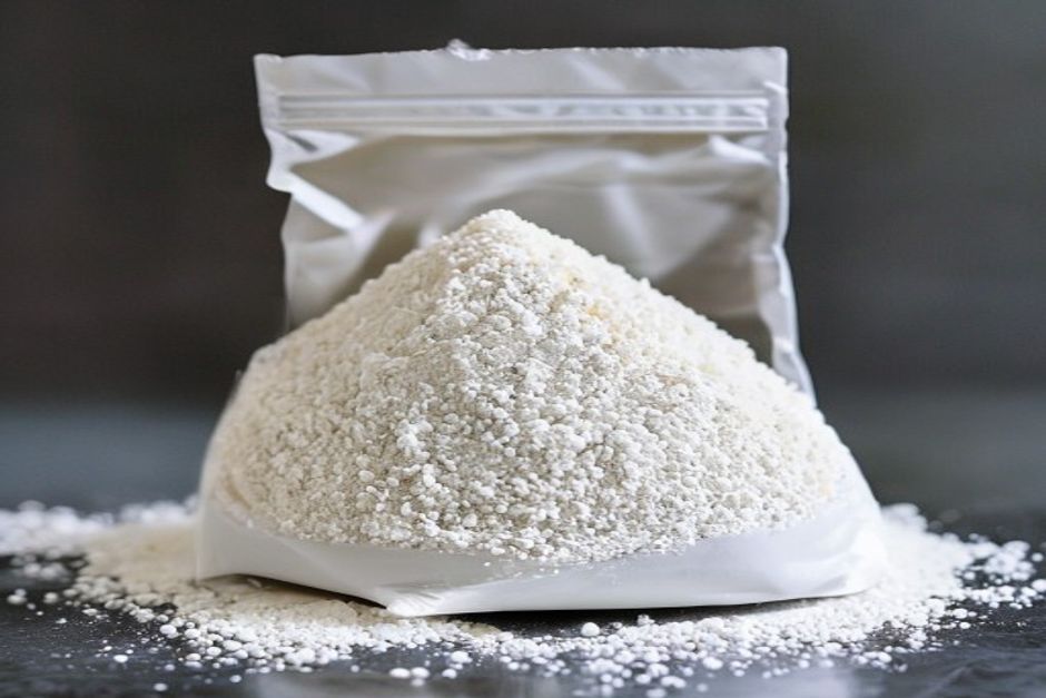
Two ceramic coating chemistries dominate the 2026 market. Boehmite (γ-AlOOH, aluminum oxyhydroxide) is the lower-cost option at 2,500-3,500 USD/mt for the raw material, with high BET surface area (120-280 m²/g) for electrolyte wettability but moderate hot-box survival (150-170 °C). α-Al2O3 (calcined alpha alumina) is the higher-performance option at 3,800-5,200 USD/mt, with low surface area (3-8 m²/g) but high hot-box survival (200-220 °C). The 2024-2026 trend in the global separator industry is a clear shift from pure boehmite coatings (which dominated 2018-2022) to α-Al2O3 single-layer or α-Al2O3/boehmite hybrid coatings (which dominate 2026+). The choice depends on the cell application: consumer electronics cells (cylindrical 18650/21700 for power tools, prismatic for phones) typically use boehmite at 2-4 g/m² per side; EV pouch and prismatic cells typically use α-Al2O3 at 3-5 g/m² per side; high-end EV cells and ESS cells use hybrid α-Al2O3/boehmite at 4-6 g/m² per side.
The Two Chemistries: Boehmite (γ-AlOOH) and α-Al2O3 Compared at the Atomic Level
Boehmite (γ-AlOOH) and α-Al2O3 are both alumina-based materials, but they differ in crystal structure, water content, density, surface area, hardness, and thermal behavior. The differences are not academic — they directly determine the coating performance in a Li-ion cell.
Boehmite (γ-AlOOH): Orthorhombic crystal structure with lattice parameters a = 3.69 Å, b = 12.23 Å, c = 2.87 Å. The unit cell contains 4 formula units (4 AlOOH). Boehmite has 15 wt% chemically bound water in the form of structural hydroxyl groups (Al-OH), released as water vapor at 450-550 °C upon endothermic dehydration to γ-Al2O3. The theoretical density is 3.07 g/cm³, but the tap density of the spray-dried powder used in separator coating is 0.4-0.7 g/cm³ due to the high porosity of the agglomerates. BET surface area is 120-280 m²/g, dominated by the internal porosity of the boehmite crystallites (intra-particle pores 2-10 nm). Mohs hardness is 3.0-3.5 — boehmite is soft and wears coating equipment slowly. Refractive index is 1.62-1.65, so boehmite-coated separator has a slightly hazy appearance (transmission 70-85% vs 92-95% for uncoated PE).
α-Al2O3 (corundum): Trigonal (rhombohedral) crystal structure with lattice parameters a = 4.76 Å, c = 12.99 Å. The unit cell contains 6 formula units (6 Al2O3), so the primitive cell contains 12 Al and 18 O. α-Al2O3 has zero chemically bound water — only physically adsorbed moisture (typically below 0.2 wt% as shipped). The theoretical density is 3.99 g/cm³, and the tap density of the calcined and milled powder is 0.7-1.1 g/cm³. BET surface area is 3-8 m²/g, dominated by the external surface of the dense particles (intra-particle pores are absent in fully calcined α-Al2O3). Mohs hardness is 8.5-9.0 — α-Al2O3 is the same hardness as silicon carbide and corundum, and wears coating equipment significantly faster than boehmite. Refractive index is 1.76-1.78, so α-Al2O3-coated separator has a slightly less hazy appearance than boehmite (transmission 75-88%).
The dehydration of boehmite is the key thermal stability concern. At 450-550 °C, the endothermic reaction is:
2 γ-AlOOH → γ-Al2O3 + H2O (vapor), ΔH = +88 kJ/mol water
This reaction releases 15 wt% of the boehmite mass as water vapor. In a separator coating, the released water can be reabsorbed by the electrolyte, diluting the salt concentration and degrading ionic conductivity. More critically, the dehydration causes a 25-30% volume shrinkage of the boehmite particle, which generates microcracks in the coating layer and degrades the coating integrity. For Li-ion cell operation, the cell temperature rarely exceeds 100 °C in normal service, so the boehmite dehydration is not a direct concern. But for abuse conditions (thermal runaway, fire exposure), the dehydration releases water vapor inside the cell, which can accelerate the failure mode. The 2026 industry consensus is that boehmite-only coating is acceptable for cells that operate below 60 °C and pass a 150-170 °C hot box test, but inadequate for cells that must pass 180-200 °C hot box test or operate above 80 °C continuously (EV fast charge, ESS in hot climates).
The thermal mass difference is also significant. At 25 °C, the specific heat capacity of boehmite is 1.10 J/(g·K) vs 0.77 J/(g·K) for α-Al2O3. On a per-mass basis, boehmite stores more heat, but the heat storage goes partly to dehydration above 450 °C. On a per-volume basis (after accounting for density), α-Al2O3 stores 1.5-2x more heat per unit volume than boehmite because the higher density (0.85 g/cm³ tap density vs 0.55 g/cm³ for boehmite) compensates for the lower specific heat. The result is that α-Al2O3 coating acts as a more effective heat sink during the first 30-60 seconds of a thermal runaway event, buying time for the battery management system to detect the failure and trigger cell isolation.
Particle Size Selection: D50 0.3-1.2 μm and the Span (D90/D10) Trade-Off
The ceramic particle size is the single most important physical parameter for separator coating. Too large, and the coating is rough and pinhole-prone. Too small, and the coating slurry is too viscous to process. The optimal D50 is in the 0.3-1.2 μm range, depending on the coating weight target and the separator base film thickness.
The D50 0.5-0.8 μm band is the workhorse for the majority of consumer electronics and EV cells. At this size, the coating slurry at 45-55 wt% solids has a viscosity of 200-600 cP, processable in a standard slot-die or gravure coater. The dry coating is 3-6 μm thick with Rz 1.5-2.5 μm surface roughness, which is smooth enough to avoid internal shorts in the cell winding process. The coating weight is 3-6 g/m² per side, and the pinhole density is below 0.1 per m² at 12 μm PE base film. The hot-box survival temperature is 180-200 °C for α-Al2O3 and 150-170 °C for boehmite.
The D50 0.2-0.4 μm band is the niche for ultra-thin separators (5-9 μm PE base film) used in high-energy-density EV cells (350-400 Wh/kg gravimetric). The smaller particle size is needed to maintain the coating uniformity at 1-2 g/m² per side — a 0.5 μm particle on a 1.5 g/m² coating covers only 30-50% of the base film surface, while a 0.3 μm particle covers 50-70% and gives better pinhole resistance. The trade-off is higher slurry viscosity (400-1,000 cP at 50 wt% solids), which requires more dispersant (0.5-1.0 wt% PAA vs 0.3-0.5 wt% PAA) and slower line speed (20-40 m/min vs 30-80 m/min). The 2026 production yield for sub-0.3 μm α-Al2O3 coating is 88-93%, compared to 92-97% for the 0.5-0.8 μm band.
The D50 1.0-1.5 μm band is the legacy standard, used in the first generation of ceramic-coated separators (2015-2020). At this size, the coating weight is 5-10 g/m² per side and the hot-box survival is excellent (200-220 °C), but the coating is rough (Rz 3-5 μm) and adds significant thickness (5-10 μm per side). The trend in 2024-2026 is to use the smaller D50 to reduce coating weight while maintaining hot-box performance.
The span value (D90-D10)/(D50) or D90/D10 ratio is the second most important parameter. A monomodal D50 0.7 μm powder with span 1.5-2.5 packs more densely than a bimodal D50 0.7 μm powder with span 3.5-4.5. The packing density directly affects the coating porosity, the pinhole density, and the peel strength. The 2026 industry benchmark for high-quality separator coating is span 2.0-3.0 for boehmite and span 1.5-2.5 for α-Al2O3. Span values above 3.5 produce coatings with 3-5x higher pinhole density and 20-30% lower peel strength. The pinhole density is measured by a high-voltage pinhole test (5-10 kV DC applied across the coating, current above 1 μA indicates a pinhole) and is typically below 0.05 per m² for a well-controlled production line.
Coating Weight: 2-8 g/m² and the Energy Density Trade-Off
Coating weight is the most variable parameter across the Li-ion industry. The choice is driven by a trade-off between safety (higher coating weight = better hot-box survival) and cell performance (higher coating weight = lower ionic conductivity, lower energy density, higher cost). The 2026 industry standard bands are:
| Cell Application | Coating Weight (g/m² per side) | Total (g/m²) | Hot-Box Survival | Separator Cost (USD/m²) |
|---|---|---|---|---|
| Cylindrical 18650/21700 (consumer, power tool) | 2-3 (boehmite) | 4-6 | 150-170 °C | 0.8-1.2 |
| Prismatic phone battery | 2-4 (boehmite or α-Al2O3) | 4-8 | 150-180 °C | 1.0-1.5 |
| EV pouch cell (LFP) | 3-5 (α-Al2O3 or hybrid) | 6-10 | 180-200 °C | 1.3-2.0 |
| EV prismatic cell (NMC811) | 3-5 (α-Al2O3 hybrid) | 6-10 | 200-220 °C | 1.5-2.2 |
| Energy Storage System (ESS) prismatic | 4-6 (α-Al2O3 hybrid) | 8-12 | 200-220 °C | 1.8-2.5 |
| High-power 4680 cylindrical (Tesla-style) | 2-3 (α-Al2O3, thin) | 4-6 | 180-200 °C | 1.2-1.7 |
The relationship between coating weight and hot-box survival is approximately linear. Going from 2 g/m² to 4 g/m² per side raises the hot-box survival by 15-25 °C (e.g., from 170 °C to 195 °C for α-Al2O3). Going from 4 g/m² to 6 g/m² raises the hot-box survival by another 5-10 °C (e.g., from 195 °C to 205 °C). The diminishing return above 6 g/m² means that the optimal coating weight for most applications is 3-5 g/m² per side — enough hot-box margin to pass the 200 °C test, but not so much that the ionic conductivity and energy density suffer.
The relationship between coating weight and ionic conductivity is approximately inverse-linear. At 1 M LiPF6 in EC/EMC (1:1 v/v) at 25 °C, the ionic conductivity drops from 0.85 mS/cm for uncoated PE to 0.78 mS/cm at 2 g/m², 0.72 mS/cm at 4 g/m², and 0.65 mS/cm at 6 g/m² per side. The reduction is driven by the longer electrolyte path through the ceramic layer, partially offset by the higher porosity of the ceramic (50-60 vol% vs 40-45 vol% for uncoated PE). At -20 °C, the trend reverses — ceramic-coated PE has 10-30% higher ionic conductivity than uncoated PE because the ceramic particles prevent the electrolyte from freezing in the pores, maintaining the ionic transport pathway at low temperature.
The relationship between coating weight and cell energy density is straightforward. Each gram of ceramic coating per m² of separator adds 0.6-0.8 cm³ of coating volume (at 0.7-0.85 g/cm³ tap density after calendering). For an EV cell with 25 m² of separator total, going from 2 g/m² to 4 g/m² per side adds 50-100 cm³ of coating volume, which displaces 50-100 cm³ of electrode active material — a 0.3-0.6% reduction in cell energy density. The trade-off is acceptable for the safety improvement, and many cell designs now use thinner PE base film (9-12 μm vs 16-20 μm) to offset the coating volume.
Thermal Stability: Hot Box Test, Thermal Shrinkage, and the GB 38031 Standard
The hot box test is the critical safety test for Li-ion cells. The test is defined in IEC 62660-2 (international), GB 38031-2020 (China, updated 2025 to GB 38031-2025), UL 2580 (US), and EU ECE R100.3 (EU). The test procedure is: (1) fully charge the cell to 100% state-of-charge (SOC) using the manufacturer's standard charge protocol; (2) place the cell in a temperature-controlled chamber; (3) ramp the chamber temperature to the test target (130 °C for GB 38031-2020, 150 °C for IEC 62660-2, 180 °C for UL 2580, 200 °C for GB 38031-2025 and the latest EV cell requirements); (4) hold at the test temperature for 1-2 hours; (5) monitor cell temperature and voltage for signs of thermal runaway (cell temperature rise above 60 °C, voltage drop to below 1 V, or fire/explosion). A pass requires that the cell does not catch fire or explode during the test, and that the cell temperature rise is below 60 °C above the chamber temperature.
The ceramic coating on the separator is what allows the cell to pass the 180-200 °C hot box test. At 130 °C, uncoated PE separator shrinks 30-50% in 30 minutes (the polyethylene softens above its melting point of 115-130 °C and the oriented crystalline structure relaxes, causing macroscopic shrinkage). The shrinkage exposes the anode and cathode to direct contact at the edge of the cell, where the winding tension is lowest, creating an internal short. The internal short then drives local Joule heating, which drives the cell temperature above 200 °C within seconds, triggering electrolyte decomposition and thermal runaway. With a 3-5 g/m² per side α-Al2O3 coating, the PE film is mechanically constrained by the ceramic layer — the coating prevents the PE from shrinking, maintains the separation between anode and cathode, and the cell passes the hot box test.
Thermal shrinkage at 150 °C/1 h is a standard quality-control test for ceramic-coated separator. The test measures the dimensional change of a 100 mm x 100 mm separator sample after heating in an oven at 150 °C for 1 hour. The acceptance criteria for EV-grade separator is below 2% shrinkage in both machine direction (MD) and transverse direction (TD). For consumer-grade separator, the criterion is below 3% MD/TD. For ESS-grade separator, the criterion is below 1.5% MD/TD. Uncoated PE typically shows 30-50% MD and 20-40% TD shrinkage at 150 °C/1 h. Boehmite-coated PE (3 g/m² per side) shows 2-4% MD and 1-3% TD. α-Al2O3-coated PE (3 g/m² per side) shows 1-2% MD and 0.5-1.5% TD. Hybrid α-Al2O3/boehmite coating (4 g/m² per side) shows 0.5-1.5% MD and 0.3-1.0% TD.
The thermal stability advantage of α-Al2O3 over boehmite is most pronounced above 170 °C. Below 150 °C, the two materials perform similarly because the PE base film has not yet softened significantly. Between 150 and 200 °C, the α-Al2O3 coating maintains its structural integrity while the boehmite coating starts to shrink and microcrack due to the partial dehydration of the surface boehmite. Above 200 °C, the α-Al2O3 coating continues to hold the PE film in place while the boehmite coating has fully dehydrated and lost its mechanical strength. The hot-box survival temperature is the temperature at which the coating fails to hold the PE film and the cell goes into thermal runaway. For boehmite, this is 150-170 °C. For α-Al2O3, this is 200-220 °C. For hybrid coating, this is 200-210 °C.
The puncture strength of the separator is also a critical safety parameter. A nail penetration test (3 mm diameter steel nail, 1 m/s penetration speed through a fully charged cell) drives an internal short that simulates a manufacturing defect or a crash-induced internal short. The ceramic coating increases the puncture strength from 200-300 g for uncoated PE to 400-600 g for boehmite-coated and 500-800 g for α-Al2O3-coated. The higher puncture strength delays the internal short by 10-30 seconds, buying time for the cell to distribute the heat and reducing the peak temperature rise. The 2026 industry standard for EV cells is puncture strength above 500 g, which requires α-Al2O3 or hybrid coating at 3-5 g/m² per side.
Ionic Conductivity and Electrolyte Wettability: The Two Performance Trade-Offs
Ionic conductivity and electrolyte wettability are the two cell-performance parameters that are most affected by the ceramic coating. The ceramic coating reduces ionic conductivity by 5-20% but improves electrolyte wettability by 30-100%. The net cell-level performance is typically neutral or slightly positive, because the improved wettability reduces the cell formation time and improves the low-temperature performance.
Ionic conductivity is measured on a separator sample soaked in 1 M LiPF6 in EC/EMC/DMC (1:1:1 v/v/v) at 25 °C, using a four-probe AC impedance method (frequency 1 kHz to 1 MHz). The measurement cell has two stainless steel blocking electrodes with the separator in between, and the resistance is extracted from the high-frequency intercept of the Nyquist plot. The separator thickness is measured by a micrometer at 5 points and the average is used to calculate the conductivity (σ = L / (R × A), where L is thickness, R is resistance, A is electrode area). The 2026 industry benchmark for high-quality ceramic-coated separator is 0.7-0.9 mS/cm at 25 °C and 0.15-0.25 mS/cm at -20 °C.
| Coating Type | Ionic Conductivity at 25 °C (mS/cm) | Ionic Conductivity at -20 °C (mS/cm) | Electrolyte Uptake (wt%) | Gurley (s/100 mL) |
|---|---|---|---|---|
| Uncoated PE (16 μm) | 0.85-0.95 | 0.08-0.12 | 100-150 | 180-220 |
| Boehmite-coated PE (3 g/m²/side) | 0.70-0.85 | 0.15-0.22 | 200-280 | 220-280 |
| α-Al2O3-coated PE (3 g/m²/side) | 0.65-0.80 | 0.13-0.20 | 220-300 | 250-320 |
| Hybrid α-Al2O3/boehmite (4 g/m²/side) | 0.70-0.85 | 0.16-0.24 | 240-320 | 240-300 |
| Uncoated PP (25 μm) | 0.80-0.90 | 0.05-0.10 | 80-120 | 350-450 |
The Gurley number is the time required to pass 100 mL of air through 1 square inch of separator under a pressure differential of 0.879 psi (6.06 kPa). Lower Gurley = higher porosity = higher ionic conductivity. The ceramic coating increases the Gurley number by 30-80% compared to uncoated PE because the coating adds resistance to air flow. The trade-off is that the ceramic coating has higher porosity (50-60 vol%) than the PE film (35-45 vol%) and the higher porosity of the coating partially offsets the longer air path. The 2026 industry benchmark for ceramic-coated separator is Gurley 200-300 s/100 mL, which is acceptable for most Li-ion cell applications.
Electrolyte wettability is measured by the electrolyte uptake test: a 50 mm x 50 mm separator sample is weighed dry, soaked in 1 M LiPF6 in EC/EMC (1:1 v/v) for 30 minutes, drained, blotted dry, and weighed wet. The uptake is calculated as (wet mass - dry mass) / dry mass × 100%. Uncoated PE has 100-150 wt% uptake, boehmite-coated PE has 200-280 wt%, α-Al2O3-coated PE has 220-300 wt%, and hybrid has 240-320 wt%. The higher uptake for the ceramic coatings is driven by the higher porosity and the hydrophilic surface of the ceramic (boehmite is more hydrophilic than α-Al2O3, but α-Al2O3 has higher porosity). The cell-level benefit of higher uptake is faster electrolyte absorption during cell formation (24-48 hours vs 48-72 hours for uncoated PE) and better low-temperature performance (the electrolyte remains in the liquid phase at -20 °C in the ceramic pores).
The contact angle of the electrolyte on the separator surface is the surface-level wettability metric. A 5 μL droplet of 1 M LiPF6 in EC/EMC is placed on the separator surface and the contact angle is measured by a goniometer after 5 seconds. Uncoated PE has a contact angle of 35-45° (hydrophilic surface, the PE has been corona-treated to improve wettability). Boehmite-coated PE has 15-25° (very hydrophilic, the boehmite surface has many -OH groups). α-Al2O3-coated PE has 20-30° (hydrophilic, but less so than boehmite). The contact angle correlates with the cell fill speed — a separator with lower contact angle fills with electrolyte faster, reducing the cell formation time and improving the production throughput.
Coating Process: Slot-Die vs Gravure, Slurry Rheology, and Drying
The ceramic coating is applied to the PE base film by either slot-die coating or gravure coating. Both methods use an aqueous slurry of the ceramic powder, a polymer binder, a dispersant, and deionized water. The slot-die method is the more common for high-end separator (used by Asahi Kasei, Toray, SK Innovation, and the Chinese leaders Senior, SEMCORP, and Gellec). The gravure method is used for high-volume low-end separator (used by some Chinese second-tier manufacturers).
Slot-die coating: The slurry is pumped through a precision slot-die head with a 30-100 μm gap, which deposits a uniform wet film on the PE base film moving at 30-80 m/min. The wet film thickness is controlled by the slurry flow rate, the line speed, and the slot-die gap. Typical wet film thickness is 30-100 μm, which dries to a 3-8 μm dry coating. The slot-die method gives excellent thickness uniformity (variation below ±5%) and works well for both single-side and double-side coating (double-side is achieved by passing the film through two slot-die heads in series, one on each side). The capital cost is high ($2-5 M for a complete line), but the throughput is high (10-30 million m²/year) and the yield is excellent (92-97%).
Gravure coating: The slurry is picked up by a gravure cylinder (engraved with 50-200 lines per inch) and transferred to the PE base film by a rubber pressure roller. The wet film thickness is controlled by the gravure line count and the gravure cell volume. Typical wet film thickness is 10-40 μm, which dries to a 1-4 μm dry coating. The gravure method gives lower thickness uniformity (variation ±10-15%) but works well for thin coatings. The capital cost is lower ($0.5-1.5 M for a complete line), and the throughput is 15-40 million m²/year. The yield is 85-92%, lower than slot-die because of the gravure cell pattern that can produce a stripe texture on the coating.
The aqueous slurry formulation is critical to the coating quality. The standard formulation is:
- Ceramic powder: 35-55 wt% (boehmite or α-Al2O3, D50 0.5-1.0 μm)
- Polymer binder: 1-3 wt% (typically PVDF-HFP Kynar 2751, SBR Styronal ND430, or CMC)
- Dispersant: 0.3-1.0 wt% (typically polyacrylic acid PAA, sodium polyacrylate, or ammonium polyacrylate)
- Defoamer: 0.1-0.3 wt% (silicone-based, e.g., BYK-028 or equivalent)
- Wetting agent: 0.1-0.5 wt% (non-ionic surfactant, e.g., Triton X-100 or equivalent)
- pH adjuster: 0-0.5 wt% (NH4OH to raise pH to 8-10 for boehmite stability)
- Deionized water: balance (40-60 wt%)
The slurry viscosity at 25 °C and shear rate 100 s⁻¹ is typically 200-800 cP for slot-die and 50-200 cP for gravure. The viscosity is controlled by the solids content, the dispersant type and concentration, and the pH. For boehmite, the pH must be maintained at 8-10 to prevent gelation (boehmite is a colloidal material that gels below pH 6 and above pH 11). For α-Al2O3, the pH can be 6-10 because α-Al2O3 is a non-colloidal material. The slurry must be de-aired before coating (vacuum deaeration at 50-100 mbar for 30-60 minutes) to prevent pinhole formation in the dry coating from air bubbles.
The drying process is the most critical part of the coating line. The wet film is passed through a floating-air oven (also called a flotation dryer) at 50-90 °C for 10-30 seconds. The air is blown from both sides of the film at 5-15 m/s, supporting the film in the air and preventing it from touching the oven rollers. The drying temperature is a critical control parameter — too hot (above 100 °C) and the PE base film shrinks from the heat, causing the coating to crack; too cool (below 40 °C) and the drying is too slow, allowing the coating to sag and producing an uneven thickness. The optimal drying temperature for 12-25 μm PE base film is 60-80 °C, with a residence time of 15-25 seconds. The dry coating contains 0.5-1.5 wt% residual moisture (measured by Karl Fischer), which is acceptable for the cell assembly process.
The calendering step after drying compresses the coating layer and improves the surface smoothness. The coated film is passed between two heated rollers (60-80 °C) at a linear pressure of 50-150 kg/cm. The calendering reduces the coating thickness by 20-40% and the surface roughness from Rz 3-5 μm (after drying) to Rz 1-2 μm (after calendering). The lower Rz is important for cell winding — a rough coating can protrude into the electrode during winding and create a micro-short. The calendering also improves the coating density (from 0.5-0.7 g/cm³ to 0.7-0.9 g/cm³) and the peel strength (from 100-200 N/m to 200-400 N/m).
Purity Requirements: Why Fe, Na, SO4, and Heavy Metals Must Be Below 30, 100, 100, and 5 ppm
The purity of the ceramic coating alumina is a critical quality parameter because the impurities dissolve into the electrolyte during cell operation and degrade the cell performance. The 2026 industry purity standard for separator-grade α-Al2O3 is:
| Impurity | EV Cell Spec (ppm) | ESS Cell Spec (ppm) | Consumer Cell Spec (ppm) | Effect on Cell |
|---|---|---|---|---|
| Fe2O3 | ≤ 30 | ≤ 20 | ≤ 50 | Shuttle to cathode, SEI degradation |
| Na2O | ≤ 100 | ≤ 50 | ≤ 200 | Electrolyte decomposition, gas generation |
| K2O | ≤ 50 | ≤ 30 | ≤ 100 | Similar to Na2O, less severe |
| SiO2 | ≤ 200 | ≤ 150 | ≤ 300 | HF generation, capacity fade |
| CaO | ≤ 100 | ≤ 50 | ≤ 200 | Internal resistance rise |
| MgO | ≤ 50 | ≤ 30 | ≤ 100 | Internal resistance rise |
| SO4²⁻ | ≤ 100 | ≤ 50 | ≤ 200 | Aluminum current collector corrosion |
| Cl⁻ | ≤ 50 | ≤ 30 | ≤ 100 | Aluminum current collector pitting |
| Pb, Cd, Hg, As (each) | ≤ 5 | ≤ 2 | ≤ 10 | Toxicity, environmental compliance |
Iron (Fe) is the most concerning impurity because it catalyzes the decomposition of the SEI (solid-electrolyte interphase) layer on the anode. Iron ions dissolve into the electrolyte (especially at the cathode where the potential is high, above 4.0 V vs Li/Li+), migrate to the anode, and are reduced to metallic iron nanoparticles. The metallic iron nanoparticles then catalyze the reduction of the electrolyte solvent, regenerating the SEI layer. The continuous SEI regeneration consumes lithium ions and electrolyte, causing capacity fade (typically 5-15% loss per 1,000 ppm Fe in the coating). For EV cells that must achieve 1,500-3,000 cycles, the Fe limit is set at 30 ppm (or below) to limit the capacity fade to below 5% over the cell life.
Sodium and potassium ions are exchanged into the electrolyte and reduce the lithium-ion transference number. The lithium-ion transference number is the fraction of the total ionic current carried by lithium ions (vs the anion, typically PF6⁻). For an uncoated separator with 1 M LiPF6 in EC/EMC, the transference number is 0.25-0.35. With Na or K contamination above 100 ppm in the coating, the transference number drops to 0.20-0.28, which increases the cell polarization at high current (3C-5C fast charge) and reduces the usable capacity. The 2026 industry limit of 100 ppm Na2O is the consensus number that keeps the transference number drop below 0.02.
Sulfate (SO4²⁻) and chloride (Cl⁻) are particularly aggressive toward the aluminum current collector at the cathode side. At cathode potentials above 4.0 V vs Li/Li+, the aluminum current collector is normally passivated by a thin Al2O3/AlF3 layer that prevents dissolution. Sulfate and chloride ions attack this passivation layer, causing pitting corrosion that releases Al3+ ions into the electrolyte. The Al3+ ions then migrate to the anode and are reduced to metallic aluminum, which deposits on the anode and blocks the lithium intercalation sites. The result is rapid capacity fade (5-20% in the first 100 cycles) and high internal resistance. The 2026 industry limit of 100 ppm SO4²⁻ and 50 ppm Cl⁻ is the consensus number that keeps the aluminum corrosion current density below 0.1 μA/cm² at 4.3 V vs Li/Li+.
Aluminaworld AW-CCA-LIB is a high-purity α-Al2O3 grade produced from aluminum hydroxide (ATH, Al(OH)3) via calcination at 1,200-1,300 °C. The ATH is Bayer-process aluminum hydroxide (purity 99.7-99.85 wt% Al2O3 equivalent) with Fe2O3 below 100 ppm and Na2O below 300 ppm. The calcination converts the ATH to α-Al2O3 via the sequence ATH → amorphous Al2O3 → γ-Al2O3 → δ-Al2O3 → θ-Al2O3 → α-Al2O3, with the final phase transition at 1,200-1,300 °C producing the thermodynamically stable α phase. The calcined material is then acid-washed (with dilute HCl or H2SO4) to remove the surface Na and K, rinsed with deionized water to remove the residual acid, and dried. The final AW-CCA-LIB has 99.85-99.92 wt% Al2O3, Fe2O3 below 30 ppm, Na2O below 100 ppm, and SO4²⁻ below 50 ppm.
Slurry Formulation, Dispersant Chemistry, and Viscosity Control
The slurry formulation is the single most controllable parameter in the separator coating process. The slurry must be stable (no settling for 24+ hours), processable (viscosity 100-800 cP at the coating shear rate), and compatible with the PE base film (no chemical attack on the PE). The four key components are ceramic powder, binder, dispersant, and water.
The binder is the film-forming polymer that holds the ceramic particles together and adheres the coating to the PE base film. Three binder types are common in the 2026 separator industry:
- PVDF-HFP (polyvinylidene fluoride-hexafluoropropylene): Kynar 2751 or Solef 21216. Used in 40-50% of separator coating lines, especially for high-end EV cells. PVDF-HFP has excellent chemical resistance to the electrolyte, good adhesion to PE (peel strength 200-400 N/m), and high thermal stability (melting point 140-150 °C). The disadvantage is the need for an organic solvent (NMP or DMF) for the binder solution, which complicates the aqueous slurry and requires a separate binder emulsion step. Recent development of PVDF-HFP aqueous emulsions (e.g., Kynar Aquatec) allows the binder to be used in a fully aqueous slurry.
- SBR (styrene-butadiene rubber): Styronal ND430 or JSR TRD-2001. Used in 30-40% of separator coating lines, especially for consumer electronics. SBR is a water-based emulsion that is easy to formulate and gives a flexible coating. The disadvantage is the lower chemical resistance to the electrolyte (SBR swells 5-15% in EC/EMC) and the lower thermal stability (glass transition -10 to +10 °C, melting point 100-120 °C).
- CMC (carboxymethyl cellulose): Used in 10-20% of separator coating lines, especially for low-end consumer cells. CMC is water-soluble, easy to formulate, and gives a moderately flexible coating. The disadvantage is the lower chemical resistance to the electrolyte (CMC is partially soluble in the EC solvent) and the lower peel strength (100-200 N/m).
The dispersant is the key to a stable, low-viscosity slurry. The dispersant adsorbs on the ceramic particle surface and provides electrostatic and/or steric repulsion between particles. For α-Al2O3 (non-colloidal, isoelectric point at pH 8-9), the dispersant is typically an anionic polyelectrolyte (sodium polyacrylate, ammonium polyacrylate, or polyacrylic acid) at 0.3-1.0 wt% on a dry ceramic basis. The polyacrylate adsorbs on the Al2O3 surface and provides a negative charge at pH above 9, which electrostatically repels the particles. For boehmite (colloidal, isoelectric point at pH 9-10), the dispersant is a non-ionic polymer (polyvinylpyrrolidone PVP, polyethylene oxide PEO) at 0.5-2.0 wt%, which provides steric repulsion without the pH sensitivity.
The slurry pH is a critical control parameter. For α-Al2O3, the pH must be maintained at 9-10.5 to keep the particles fully de-agglomerated and the slurry stable. At pH below 8, the particles carry a low charge and the slurry viscosity rises sharply (from 300 cP to 1,000+ cP). At pH above 11, the particles dissolve (especially the surface Al2O3 dissolves to Al(OH)4⁻) and the slurry becomes unstable. The pH is adjusted with NH4OH (ammonia) for α-Al2O3 and with HNO3 for boehmite. The ammonia also helps to prevent the growth of bacteria in the aqueous slurry (a common problem in warm and humid production environments).
The slurry aging is another important parameter. Freshly prepared slurry has a different viscosity than aged slurry (24-48 hours at 25 °C). For α-Al2O3 with polyacrylate dispersant, the viscosity drops by 10-20% over the first 24 hours as the dispersant fully adsorbs on the particle surface, then stabilizes. For boehmite with PVP dispersant, the viscosity rises by 10-20% over the first 24 hours as the boehmite gel structure develops, then stabilizes. The standard practice is to age the slurry for 24 hours before coating and to use it within 72 hours of preparation.
Relevant Standards: GB 38031, IEC 62660, UL 2580, ECE R100, and Material Test Methods
Seven standards cover the ceramic-coated separator specification, testing, and application. The user should be familiar with at least the first four before specifying or accepting a ceramic-coated separator.
- GB 38031-2025 (China, EV Battery Safety) — Mandatory safety standard for electric vehicle traction batteries. Requires hot box test at 200 °C/2 h without thermal runaway, plus thermal shock, overcharge, over-discharge, short circuit, and drop tests. The 2025 update tightens the hot box test from 130 °C (2020 version) to 200 °C.
- IEC 62660-2 (International, Li-ion Cell Performance) — Standard test methods for Li-ion cells for EV applications. Includes hot box test at 150 °C/1 h, thermal abuse, mechanical shock, and external short. Used as the international reference for cell qualification.
- UL 2580 (US, EV Battery Safety) — Underwriters Laboratories standard for batteries in EV applications. Includes hot box test at 180 °C/1 h, overcharge, over-discharge, short circuit, and drop tests. Used for North American market access.
- EU ECE R100.3 (EU, EV Battery Safety) — UNECE Regulation No. 100, Revision 3. Includes hot box test at 180 °C/1 h, vibration, thermal shock, and overcharge. Mandatory for EV batteries sold in the EU.
- UL 1642 (US, Lithium Cell Safety) — Underwriters Laboratories standard for lithium cells. Includes hot box test at 150 °C/1 h, short circuit, overcharge, drop, and impact tests. Used for consumer electronics and ESS cells.
- ASTM D5946 (Separator Thickness and Basis Weight) — Standard test method for separator thickness (mechanical micrometer) and basis weight (gravimetric). Used for QC of incoming and finished separator.
- ASTM D7263 (Separator Ionic Conductivity) — Standard test method for ionic conductivity of separator using AC impedance. Used for QC of finished separator.
For material specification of the ceramic coating powder, three additional standards are relevant:
- ISO 9001:2015 — Quality management system. Required for the ceramic powder manufacturer. Aluminaworld is ISO 9001:2015 certified by TUV SUD (certificate valid until 2027).
- ISO 22489 (Fine Ceramic Powder Particle Size by Laser Diffraction) — Standard test method for D10, D50, D90 measurement. Used for QC of the ceramic powder.
- ASTM E2658 (Surface Area by BET) — Standard test method for BET surface area of fine powders. Used for QC of the ceramic powder.
Hybrid Coatings: Bilayer and Blended Designs for 2026 EV Cells
Hybrid boehmite + α-Al2O3 coatings are the dominant 2026 design for high-end EV cells. The two architectures are bilayer (separate boehmite and α-Al2O3 layers) and blended (single mixed layer).
Bilayer architecture: The inner layer (touching the PE film) is boehmite at 1-2 g/m² per side, applied in the first slot-die station. The outer layer (touching the electrode after winding) is α-Al2O3 at 2-4 g/m² per side, applied in the second slot-die station after the boehmite layer is dried. The advantage of the bilayer is the independent optimization of each layer — the boehmite layer is optimized for adhesion to PE and electrolyte wettability, the α-Al2O3 layer is optimized for thermal stability and hot-box survival. The disadvantage is the higher capital cost (two slot-die stations, two drying ovens) and the higher operating cost (two slurry preparation systems). The 2026 bilayer hybrid is used in the premium EV cell segment (NMC811/silicon-graphite cells with 300+ Wh/kg gravimetric) and accounts for about 30% of the high-end separator production.
Blended architecture: A single slurry containing 30-50 wt% boehmite and 50-70 wt% α-Al2O3 is applied in a single slot-die station at 4-6 g/m² per side. The advantage is the simpler process (one slurry, one coater, one dryer) and the lower capital cost. The disadvantage is the more complex slurry rheology — boehmite is a gel-forming colloid with high viscosity at low shear, while α-Al2O3 is a non-colloidal powder with low viscosity at low shear. The blend must be carefully formulated to give a stable, processable slurry. The 2026 blended hybrid is used in the mid-range EV cell segment (NMC622/graphite cells with 220-260 Wh/kg) and accounts for about 50% of the high-end separator production. The remaining 20% is pure α-Al2O3 single-layer, used in the highest-energy-density cells (NMC811/silicon-graphite with 320+ Wh/kg).
The 2026 industry benchmark for hybrid coating is:
- Coating weight: 4-6 g/m² per side (total 8-12 g/m²)
- Boehmite:α-Al2O3 ratio: 30:70 to 50:50
- Hot-box survival: 200-220 °C/2 h with less than 2% thermal shrinkage
- Puncture strength: 500-700 g (above the 500 g EV cell standard)
- Ionic conductivity at 25 °C: 0.70-0.85 mS/cm
- Electrolyte uptake: 240-320 wt%
- Cycle life at 80% DOD, 1C charge/1C discharge: 1,500-3,000 cycles to 80% capacity
The future direction for hybrid coatings is functional additives that go beyond thermal stability. The 2024-2026 research pipeline includes:
- Flame-retardant ceramic coatings: Boehmite + aluminum diethylphosphinate (AlPi) at 5-10 wt% on a dry coating basis. The AlPi decomposes endothermically at 280-320 °C, releasing phosphoric acid derivatives that catalyze the charring of the PE film and suppress flaming combustion. Hot-box survival rises from 200 °C to 220-240 °C.
- Lithium-ion conductive ceramic coatings: LATP (Li1.3Al0.3Ti1.7(PO4)3) or LLZO (Li7La3Zr2O12) at 5-15 wt% on a dry coating basis. The LATP and LLZO particles are lithium-ion conductors that provide additional ionic transport pathways in the coating layer, increasing the ionic conductivity by 10-30% compared to pure α-Al2O3. Used in the first generation of solid-state battery prototypes.
- Magnetic ceramic coatings: γ-Fe2O3-doped α-Al2O3 at 2-5 wt% on a dry coating basis. The γ-Fe2O3 is superparamagnetic and can be heated by an external AC magnetic field, enabling inductive heating of the separator during fast charge at sub-zero temperatures. Used in cold-climate EV applications (Norway, Canada, northern China).
Production Defects: Pinholes, Agglomerates, Cracking, and the Yield Curve
The production yield for ceramic-coated separator is 88-97% in a well-controlled line, with the main defect modes being pinholes, agglomerates, cracking, and thickness variation. Each defect mode has a specific cause and a specific fix.
Pinholes: Small holes in the coating (5-50 μm diameter) that allow the anode and cathode to come into direct contact in the cell, creating an internal short. Pinholes are caused by air bubbles in the slurry (insufficient deaeration), by particles in the slurry larger than the coating thickness (insufficient milling or filtration), or by dust on the PE base film entering the coating (insufficient cleanroom conditions). The pinhole density is measured by a high-voltage pinhole test (5-10 kV DC applied across the coating, current above 1 μA indicates a pinhole) and is typically below 0.1 per m² for a well-controlled production line. The 2026 industry benchmark for EV-grade separator is below 0.05 pinholes per m². The fix for high pinhole density is to (1) improve the slurry deaeration (vacuum at 50-100 mbar for 30-60 minutes), (2) filter the slurry through a 10-25 μm filter before the slot-die, and (3) operate the coating line in a cleanroom (ISO Class 7 or better).
Agglomerates: Clusters of ceramic particles (50-500 μm diameter) that protrude from the coating surface. Agglomerates are caused by insufficient milling of the ceramic powder, by insufficient dispersant in the slurry, or by slurry aging that allows the dispersant to desorb. The agglomerate density is measured by visual inspection under a microscope (10-50x magnification) and is typically below 0.5 per m² for a well-controlled line. The fix is to (1) improve the milling of the ceramic powder (use a bead mill or attrition mill to break down the agglomerates to below 5 μm), (2) increase the dispersant concentration by 0.2-0.5 wt%, and (3) use the slurry within 48 hours of preparation to prevent aging.
Cracking: Network of fine cracks in the coating (1-10 μm wide) that reduce the coating integrity and the hot-box survival. Cracking is caused by excessive drying temperature (above 90 °C), excessive coating thickness (above 8 μm dry), or excessive calendering pressure (above 200 kg/cm). The crack density is measured by SEM inspection at 100-1,000x magnification and is typically zero (no visible cracks) for a well-controlled line. The fix is to (1) lower the drying temperature to 50-80 °C, (2) reduce the coating thickness to 3-6 μm dry, and (3) reduce the calendering pressure to 50-150 kg/cm.
Thickness variation: Variation in the coating thickness across the web (machine direction and transverse direction) that causes local hot spots and cold spots in the cell. Thickness variation is caused by non-uniform slurry flow in the slot-die, by non-uniform drying, or by non-uniform calendering. The thickness variation is measured by a beta gauge or X-ray gauge at 10-20 points across the web and is typically below ±5% (1 sigma) for a well-controlled slot-die line. The fix is to (1) check the slot-die lip uniformity and shim if necessary, (2) check the drying oven air flow uniformity and balance the air flow, and (3) check the calender roller parallelism and shim if necessary.
The yield curve for a new ceramic-coated separator production line typically shows 75-85% yield in the first 3-6 months (qualification and ramp-up), rising to 88-92% at 6-12 months, and stabilizing at 92-97% after 12-18 months. The main yield improvement comes from reducing the pinhole density and the agglomerate density, which together account for 60-80% of the defects in a new line. The 2026 best-in-class yield for high-volume separator production is 96-97% (Asahi Kasei Hipore, Toray Setela, SK Innovation). The Chinese leaders (SEMCORP, Senior, Gellec) are at 92-95%. The smaller Chinese second-tier manufacturers are at 85-90%.
Cost per m², Cost per kWh, and the 10-Year TCO for Ceramic-Coated Separator
The cost of ceramic-coated separator is a small fraction of the total Li-ion cell cost, but it is a significant fraction of the separator cost. The 2026 cost breakdown for a high-end EV-grade α-Al2O3-coated PE separator is:
| Cost Component | Boehmite-Coated (USD/m²) | α-Al2O3-Coated (USD/m²) | Hybrid α/γ (USD/m²) | % of Total |
|---|---|---|---|---|
| PE base film (9-12 μm) | 0.30-0.50 | 0.30-0.50 | 0.30-0.50 | 25-35% |
| Ceramic powder (boehmite or α-Al2O3) | 0.10-0.20 | 0.20-0.35 | 0.25-0.40 | 10-20% |
| Polymer binder (PVDF-HFP or SBR) | 0.05-0.10 | 0.05-0.10 | 0.08-0.15 | 5-10% |
| Other chemicals (dispersant, defoamer, pH adjuster) | 0.02-0.05 | 0.02-0.05 | 0.03-0.06 | 2-5% |
| Conversion cost (labor, energy, maintenance) | 0.20-0.35 | 0.25-0.40 | 0.30-0.50 | 20-30% |
| Depreciation of coating line | 0.10-0.20 | 0.15-0.25 | 0.20-0.35 | 10-15% |
| SG&A, R&D, profit margin | 0.10-0.20 | 0.15-0.25 | 0.20-0.30 | 10-15% |
| Total (FOB China) | 0.87-1.60 | 1.12-1.90 | 1.36-2.26 | 100% |
The cost per kWh of ceramic-coated separator is 1.5-3.5 USD/kWh for the separator itself, or 0.3-0.8% of the total cell cost (the total cell cost is 100-140 USD/kWh at the pack level). For a 75 kWh EV battery pack, the separator cost is 110-260 USD, a small fraction of the 7,500-10,500 USD pack cost. The cost premium of ceramic coating over uncoated PE is 0.5-1.5 USD/m², which translates to 0.5-1.5 USD/kWh, or 0.4-1.2% of the total cell cost.
The 10-year TCO of ceramic coating is justified by the cell-level safety improvement. A 2026 EV battery with uncoated PE separator has a thermal runaway probability of 10-30% over 10 years of operation (based on fleet data from 2015-2020 EVs with early-generation separators). A 2026 EV battery with α-Al2O3-coated PE separator has a thermal runaway probability of 0.5-2% over 10 years (based on fleet data from 2020-2025 EVs with ceramic-coated separators). The cost saving from avoided thermal runaway incidents is 50-200 USD/kWh (10-year warranty replacement cost), which is 30-130x the cost of the ceramic coating. The cost-benefit ratio is overwhelmingly in favor of ceramic coating for any application above 5 Ah nominal capacity.
Aluminaworld AW-CCA-LIB and AW-PB-SEP Procurement Specifications
Aluminaworld supplies two ceramic coating grades for Li-ion battery separator. AW-CCA-LIB is a high-purity α-Al2O3 grade optimized for single-layer α-Al2O3 coating or the α-Al2O3 layer in hybrid coating. AW-PB-SEP is a pseudo-boehmite grade optimized for boehmite coating or the boehmite layer in hybrid coating.
| Parameter | AW-CCA-LIB Specification | AW-PB-SEP Specification | Test Method |
|---|---|---|---|
| Al2O3 equivalent | 99.85-99.92 wt% | 70-75 wt% (as Al2O3) | ASTM D974 / ICP-OES |
| Crystal phase | α-Al2O3 ≥ 95% by XRD | γ-AlOOH (boehmite) ≥ 95% by XRD | XRD |
| D50 (laser diffraction) | 0.5-0.8 μm | 0.7-1.2 μm | ISO 13320 (Malvern) |
| D90 | ≤ 1.5 μm | ≤ 2.5 μm | ISO 13320 |
| Span (D90-D10)/D50 | 1.5-2.5 | 2.0-3.0 | calculated |
| BET surface area | 3-7 m²/g | 180-260 m²/g | ASTM E2658 |
| Tap density | 0.85-1.0 g/cm³ | 0.4-0.7 g/cm³ | ASTM B527 |
| Fe2O3 | ≤ 30 ppm | ≤ 50 ppm | ICP-OES |
| Na2O | ≤ 100 ppm | ≤ 200 ppm | ICP-OES / flame photometry |
| SO4²⁻ | ≤ 50 ppm | ≤ 100 ppm | ion chromatography |
| Cl⁻ | ≤ 30 ppm | ≤ 50 ppm | ion chromatography |
| Pb, Cd, Hg, As (each) | ≤ 5 ppm | ≤ 5 ppm | ICP-MS |
| Moisture (as shipped) | ≤ 0.3 wt% | ≤ 5 wt% (free moisture) | Karl Fischer |
| pH (10% aqueous slurry) | 8.5-10.5 | 6.0-8.0 | pH meter |
AW-CCA-LIB is produced from Bayer-process aluminum hydroxide via calcination at 1,200-1,300 °C, jet milling to D50 0.5-0.8 μm, acid washing to remove surface Na and SO4, and final classification to remove oversize particles. AW-PB-SEP is produced from aluminum hydroxide via digestion in NaOH solution to form sodium aluminate, neutralization with HNO3 or CO2 to precipitate the boehmite gel, aging for 24-72 hours at 60-80 °C to develop the pore structure, and spray drying to form the final powder.
Both grades are supplied in 25 kg sealed polyethylene pails (5 pails per pallet, 125 kg per pallet), 500 kg sealed cardboard drums with plastic liner (2 drums per pallet, 1 mt per pallet), or 1 mt supersacks with foil liner. Each shipment includes a lot-level Certificate of Analysis showing the test results for all 14 parameters in the table above, plus a Material Safety Data Sheet (MSDS) and a Certificate of Conformity stating that the lot meets the AW-CCA-LIB or AW-PB-SEP specification. Lead time is 7-15 days from the Zibo Shandong facility to most major Asian, European, and North American ports. Sample packs of 5 kg ship within 5 days for qualification testing.
Custom grades are available on request for special applications, with 30-60 day lead time:
- AW-CCA-LIB-FINE: D50 0.2-0.4 μm for ultra-thin separator (5-9 μm PE base film) and high-energy-density cells (350-400 Wh/kg).
- AW-CCA-LIB-HV: Higher voltage stability for 4.5 V cathode cells (LNMO, Li-rich NMC). Lower transition metal content (Fe below 10 ppm, Ni below 5 ppm).
- AW-PB-SEP-GEL: Gel form (40-50 wt% solids in water) for direct use in slurry preparation without powder dispersion. Used in separator lines that prefer to avoid the powder dispersion step.
Related Applications: Where Else Alumina Ceramic Coating Protects Li-ion Cells
Beyond the standard Li-ion separator coating, the same calcined alumina and pseudo-boehmite grades are used in four adjacent applications in the Li-ion battery and energy storage industry. Aluminaworld supplies the same AW-CCA-LIB and AW-PB-SEP grades (or slight variants) for each of these applications.
Lithium-ion battery cathode coating
Calcined α-Al2O3 is also used as a surface coating on NMC and LFP cathode particles to prevent direct contact between the cathode active material and the electrolyte. The α-Al2O3 coating (typically 1-3 wt% on a dry cathode basis) acts as a physical barrier that reduces the dissolution of transition metals (Mn, Ni, Co) into the electrolyte, especially at high voltage (above 4.3 V vs Li/Li+). The cathode coating uses a higher-D50 α-Al2O3 (1-3 μm) than the separator coating (0.5-0.8 μm) because the cathode coating is applied by a different process (dry mixing or solution coating, not slot-die). The Aluminaworld AW-CCA-CAT grade is a D50 1-3 μm α-Al2O3 optimized for cathode coating.
Solid-state battery ceramic electrolyte separator
Solid-state batteries use a solid ceramic electrolyte (typically LATP, LLZO, or sulfide glass) instead of the liquid electrolyte-soaked separator. The ceramic electrolyte is a thin (50-200 μm) dense layer of the solid electrolyte material, and the surface is often coated with a thin (1-5 μm) buffer layer of α-Al2O3 to prevent direct contact between the solid electrolyte and the lithium metal anode (which would otherwise reduce the solid electrolyte over time). The buffer coating uses the same AW-CCA-LIB grade as the separator coating, but at much lower coating weight (0.1-0.5 g/m² per side, applied by spin coating or dip coating instead of slot-die).
Aluminum current collector coating
The aluminum current collector at the cathode side is a 15-20 μm thick aluminum foil that is coated on one or both sides with a thin (1-3 μm) layer of conductive carbon (Super P, graphite, carbon nanotube) plus a ceramic binder (boehmite or α-Al2O3 at 5-15 wt% on a dry coating basis). The ceramic binder improves the adhesion of the active material coating to the aluminum foil and prevents the active material from delaminating during cell cycling. The boehmite grade is AW-PB-CC (D50 0.5-1.0 μm, BET 150-220 m²/g, optimized for cathode binder).
Battery pack thermal barrier and fire-retardant coating
The battery pack enclosure in an EV contains multiple cells, and the thermal runaway of one cell can propagate to the adjacent cells if the thermal barrier is inadequate. The standard thermal barrier is a 1-3 mm thick sheet of mica, aerogel, or ceramic-filled polymer. The ceramic-filled polymer is typically epoxy or silicone filled with 30-60 wt% α-Al2O3 or aluminum hydroxide (ATH). The Aluminaworld AW-CCA-FR grade is a D50 2-5 μm α-Al2O3 optimized for thermal barrier composites. The same grade is also used as a flame-retardant filler in EV cable insulation, where 60-65 wt% ATH provides UL94 V-0 flame rating at 1.5-2.0 mm insulation thickness.
Frequently Asked Questions
Can the same ceramic coating be used on both anode and cathode sides of the separator?
Yes. The ceramic coating on the separator is identical on both sides, with the same coating weight, composition, and thickness. The coating faces the anode on one side and the cathode on the other side. The separator is symmetric in the cross-machine direction and is wound in the cell winding process with no preference for which side faces which electrode. Some 2025-2026 research papers have proposed asymmetric coatings (e.g., boehmite on the anode side for SEI stability, α-Al2O3 on the cathode side for oxidation stability), but these are still in the research stage and are not used in commercial production.
What is the optimal coating weight for a high-energy-density 4680 cylindrical cell?
The 4680 cylindrical cell format (46 mm diameter, 80 mm height, 25-30 Ah capacity) is used in Tesla Model Y, Cybertruck, and several Chinese premium EVs. The optimal coating weight is 2-3 g/m² per side of α-Al2O3 (D50 0.5-0.8 μm) on a 9-12 μm PE base film. The total separator thickness is 15-18 μm, which is the minimum to pass the Tesla internal hot-box test at 200 °C/1 h without thermal runaway. The coating weight is at the low end of the EV range because the 4680 format has a higher cell-level safety margin (larger format, lower surface-area-to-volume ratio, better heat dissipation) than smaller pouch or prismatic cells. Going above 3 g/m² per side reduces the cell energy density by 1-2% without significant safety improvement.
How does the D50 affect the slurry viscosity and what is the maximum solids loading?
The D50 has a strong effect on the slurry viscosity. At 50 wt% solids, a D50 0.3 μm α-Al2O3 slurry has viscosity 1,500-3,000 cP (very viscous, hard to process). A D50 0.5 μm slurry has 600-1,200 cP. A D50 0.8 μm slurry has 300-700 cP. A D50 1.5 μm slurry has 100-300 cP. The trend is that smaller particles increase the viscosity exponentially because of the higher specific surface area (more dispersant needed) and the higher inter-particle friction. The maximum processable solids loading is 55-60 wt% for D50 0.8 μm, 50-55 wt% for D50 0.5 μm, and 45-50 wt% for D50 0.3 μm. Going above the maximum solids loading makes the slurry unpumpable. The 2026 industry standard is 45-55 wt% solids for slot-die coating, which gives a dry coating thickness of 3-8 μm at wet film thickness 30-80 μm.
Can calcined alumina be used as a separator in solid-state batteries?
Calcined α-Al2O3 itself is not a lithium-ion conductor and cannot be used as the solid electrolyte separator in solid-state batteries. The α-Al2O3 in the ceramic-coated separator is a passive thermal-stability layer, not an active ionic conductor. For solid-state batteries, the separator is typically LATP (Li1.3Al0.3Ti1.7(PO4)3), LLZO (Li7La3Zr2O12), or a sulfide glass (Li2S-P2S5), which is a dense 50-200 μm layer that conducts lithium ions and physically separates the anode and cathode. The α-Al2O3 in this application is used as a thin (1-5 μm) buffer coating on the lithium metal anode to prevent direct contact between the solid electrolyte and the lithium metal (which would otherwise reduce the solid electrolyte over time). The Aluminaworld AW-CCA-LIB grade is suitable for this buffer coating, with the standard specification listed above.
What is the difference between ceramic-coated separator and ceramic-filled separator?
Ceramic-coated separator has a discrete ceramic layer (3-8 μm thick) on the surface of the PE or PP base film, applied by slot-die or gravure coating. Ceramic-filled separator (also called ceramic-in-PVDF or composite separator) has the ceramic particles dispersed throughout the polymer matrix, with no discrete layer. Ceramic-filled separator is made by melt-blending the ceramic powder with PVDF, PVDF-HFP, or PAN, and then extruding the blend into a thin film. The ceramic-filled separator has more uniform ceramic distribution but lower ceramic loading (typically 20-40 wt% on a dry film basis vs 60-80 wt% for ceramic-coated). The hot-box survival for ceramic-filled separator is 150-180 °C, lower than ceramic-coated (200-220 °C). The 2026 industry trend is strongly toward ceramic-coated separator, and the ceramic-filled separator is a declining niche used in a few specialty cells.
What is the future of ceramic coating technology?
The future of ceramic coating technology is moving in three directions. (1) Higher temperature α-Al2O3 or hybrid coatings to survive 220-240 °C hot box test required by the 2027-2030 EV battery safety standards (China GB 38031-2027, EU ECE R100.4, US UL 2580B). (2) Lower D50 (sub-0.2 μm) for ultra-thin separators (5-9 μm PE base film) used in 400+ Wh/kg cells, requiring advanced dispersant chemistry and milling technology. (3) Functional coatings that add capability beyond thermal stability, including flame-retardant coatings (boehmite + AlPi), lithium-ion conductive coatings (LATP, LLZO), and magnetic coatings (γ-Fe2O3-doped). The 2030 forecast is that 80-90% of Li-ion separators for EV and ESS will be ceramic-coated with α-Al2O3 or hybrid chemistry, compared to 60-70% in 2026. The remaining 10-20% will be either uncoated PE/PP for low-cost consumer cells or entirely new separator technologies (aramid nanofiber, cellulose nanofiber, electrospun PVDF-HFP, polymer-ceramic composite).
How is the coating inspected for defects in production?
The production-line inspection of ceramic-coated separator uses four techniques in series. (1) Optical inspection: a high-resolution line-scan camera (5,000-10,000 pixels per line) inspects the coating surface for visible defects (agglomerates, pinholes, scratches, contamination). The detection limit is 50-100 μm defects at 30-80 m/min line speed. (2) High-voltage pinhole test: 5-10 kV DC is applied across the coating and the current is monitored. A current spike above 1 μA indicates a pinhole. The detection limit is 5-10 μm pinholes. (3) Beta gauge or X-ray gauge: measures the coating thickness at 10-20 points across the web with ±0.5 μm precision. The thickness map is used to identify trends and trigger process adjustments. (4) Offline QC: samples are taken every 1-2 hours and tested in the QC lab for thickness (ASTM D5946), Gurley (ASTM D7263), ionic conductivity, peel strength, thermal shrinkage, and visual appearance under a microscope. The 2026 industry benchmark for production yield is 92-97% (best-in-class 96-97% for Asahi Kasei and Toray; 92-95% for Chinese leaders SEMCORP, Senior, Gellec).
What is the shelf life of ceramic-coated separator and how should it be stored?
The shelf life of ceramic-coated separator is 12-24 months when stored properly, compared to 6-12 months for uncoated PE. The ceramic coating protects the PE from oxidation and from environmental stress cracking. The recommended storage conditions are: temperature 10-30 °C, relative humidity below 60%, away from direct sunlight, in the original sealed packaging (polyethylene bag inside a cardboard box or aluminum foil bag inside a steel drum). The separator should be allowed to equilibrate to the coating line temperature (typically 20-25 °C) for at least 4 hours before use. The first-in-first-out (FIFO) inventory principle should be followed to ensure that the oldest material is used first. The 2026 industry benchmark for separator supplier warranty is 18 months from the date of shipment, with a 100% replacement guarantee for any defect discovered within the warranty period.
Next Steps for Your Separator Coating Project
For a new separator coating line, a retrofit of an existing line, or a switch from boehmite to α-Al2O3 coating, the next step is a 30-minute technical call to review your PE base film specification (thickness, porosity, surface treatment), the target coating weight and chemistry, the coating line configuration (slot-die or gravure, single-side or double-side), the production capacity, and the cell performance requirements. We will provide a slurry formulation recommendation, a sample shipment of AW-CCA-LIB or AW-PB-SEP, and a quote for your annual volume. For R&D or qualification testing, we ship a 5 kg sample pack within 5 days. For full-scale procurement, lead time is 7-15 days from the Zibo Shandong facility.
For trial production on an existing coating line, we recommend a 100 kg pilot order of AW-CCA-LIB to validate the slurry formulation, the coating quality, and the cell performance. The trial typically takes 2-4 weeks from sample arrival to cell test results. The cost of the pilot is $1,500-3,000 for the material plus $5,000-15,000 for the cell testing, depending on the test protocol. The pilot is designed to verify the hot-box survival, the ionic conductivity, the peel strength, and the cycle life against the cell performance targets. The pilot success criteria are typically 90%+ of the cell performance targets met, with the remaining 10% addressed in the next iteration of the slurry formulation.
For large-scale procurement of 100+ mt/year, we offer framework agreements with locked-in pricing for 12 months, dedicated production capacity, and quarterly quality audits. The pricing for framework agreements is typically 15-25% below the spot market price for AW-CCA-LIB and 10-20% below the spot market price for AW-PB-SEP. The framework agreement also includes a quality guarantee (replacement of any non-conforming lot at no cost) and a supply guarantee (priority allocation in case of supply shortage). For buyers in China, we can also offer a domestic CIF price from our Zibo warehouse with 5-7 day lead time.
For pricing on AW-CCA-LIB and AW-PB-SEP in 25 kg pail, 500 kg drum, or 1 mt supersack, contact our sales team with your annual volume, D50 target, purity requirements, and destination port. Indicative pricing as of August 2026 is 3,800-5,200 USD per metric ton FOB Qingdao for AW-CCA-LIB (1-5 mt orders) and 2,500-3,500 USD per metric ton for AW-PB-SEP, with volume discounts at 10 mt and above. Freight to most major Asian ports is $150-300 per mt; to European and North American ports is $400-700 per mt. The quoted price includes the lot-level Certificate of Analysis, the Material Safety Data Sheet, and the Certificate of Conformity.
For technical questions about slurry formulation, coating weight selection, hybrid bilayer design, or cell performance optimization, contact our engineering team at barry@aluminaworld.com or via WhatsApp at +86 133 2522 2240. We respond to most technical inquiries within 4 hours during Chinese business days and within 24 hours on weekends. We can also arrange an on-site visit to your coating line for a process audit and slurry optimization, with travel cost borne by the buyer and engineering time at no charge for orders above 10 mt/year.
Request a Quote or Sample
For a quote on AW-CCA-LIB or AW-PB-SEP in 25 kg pail, 500 kg drum, or 1 mt supersack, click below to open a WhatsApp conversation with prefilled text. For email inquiries, write to barry@aluminaworld.com with your coating specification, annual volume, and destination port.
💬 WhatsApp: Quote for Separator Coating Alumina 📧 Email InquiryRelated Articles from Aluminaworld
- Calcined Alumina for Thermal Spray: alpha-Al2O3 Phase Purity Matters
- Calcined Alumina for Sapphire Substrate Polishing: D50 0.3-30 μm Selection
- Calcined Alumina for Refractory Castables: 5N vs 4N Purity Real-World Impact
- Pseudo Boehmite Alumina Content: 70% vs 75% vs 80% Selection Guide
- Pseudo Boehmite for FCC Catalyst: Gel vs Powder Property Differences
- Alumina Powder Particle Size Distribution: Laser Diffraction vs Sedimentation (Stokes)
- Alumina Powder Products (Calcined Alumina, α-Al2O3, Reactive Alumina)
- Pseudo Boehmite Products (Catalyst Carrier, Binder, Adsorbent)
- Activated Alumina Products (Adsorbent, Desiccant, Defluoridation)
- Aluminum Hydroxide (ATH) for Flame Retardant