Emergency Adsorbent Discharge System Design for Toxic Gas Release: Vent Stack Height vs LFL
1. When Does an Emergency Adsorbent Discharge Actually Happen?
Emergency discharge is not normal shutdown. It is the bounded-but-uncontrolled inventory release path used when the bed cannot be regenerated in place, cannot be cooled under feed, or cannot be held while operators isolate the upstream feed. Four scenarios dominate field experience and form the basis of API 521 Section 4.4.5 and API 2000 Annex A sizing:
- Blocked outlet / control valve failure with bed full of hydrocarbon. The most common case in PSA service. A block valve downstream of the adsorber sticks or is mistakenly closed during regeneration; the bed continues to receive feed at line pressure; the relief device on the vessel lifts; the entire bed inventory (typically 1.5–12 tonnes of molecular sieve depending on vessel size) sees a pressure spike that requires immediate depressurisation to a safe elevation.
- Fire-case external heat input. Per API 521 §4.4.5.7, the vessel shell is assumed to be wetted by a pool fire of defined duration (typically 10–30 min for hydrocarbon service, longer for refinery integration). The latent heat of the loaded adsorbent — hydrocarbon + water on molecular sieve 13X can be 12–18 wt% of inventory — is now a credible additional release load because the adsorbed hydrocarbon desorbs as the bed heats.
- Hot regeneration heater tube failure (TSA / steam-heated units). A cracked heater tube dumps combustion gas + steam into the bed, raising temperature 200–400 °C in minutes; the loaded hydrocarbon flashes off and the pressure-relief device lifts.
- Contaminated or poisoned bed requiring immediate removal. When an unexpected feed component (amine, glycol, compressor oil, H2S breakthrough to breakthrough limit) compromises the bed faster than regeneration can recover, the operator must discharge the bed to a sealed skip or vent the entire inventory. This is the case where a well-designed vent stack pays for itself the first time, because the alternative is a controlled burn-down at grade.
Each scenario produces a different release envelope: mass release rate, duration, composition, and temperature all change. The vent stack must accommodate the worst credible case, not the typical case. The relief-device sizing per API 521 (single-phase or two-phase flow) gives the mass release rate; the dispersion math (typically AERMOD or PHAST in newer projects) gives the downwind concentration profile; the LFL check gives the exclusion-zone radius.
2. Vent Stack Height vs LFL — Why the Stack Is Almost Never the Diameter You First Sketch
The single most common error in emergency-vent-stack design is sizing the stack diameter first. Operators sketch a 6" (DN150) stack because that is the size of the relief-device outlet, then build it 10 m tall, and discover at commissioning that the downwind LFL contour is far larger than the unit plot line. The actual design sequence inverts the question:
- Decide the exclusion-zone radius first. The exclusion zone is the area where the worst-credible-release dispersion envelope is above 25% of LFL (NFPA 30 / API 2000 limit for safe operator access during the release). For propane, this is roughly 60–120 m downwind depending on wind class. For H2S the envelope is shorter but the toxicity limit (10 ppm ERPG-3, 100 ppm IDLH) dominates over the LFL envelope.
- Calculate the required release height. Use AERMOD / PHAST / SCREEN3 dispersion, with the release rate from API 521 §4.4.5.13 fire-case relief sizing, to find the stack-tip elevation that puts the downwind ground-level concentration below 25% LFL at the operator-station and air-intake distances. This elevation is typically 15–35 m for an LNG-grade release, 25–45 m for refinery-grade hydrocarbon, and can exceed 60 m for an H2S service on a Class-100 site boundary.
- Then size the diameter from the release rate. Stack exit velocity at the design release rate should be 0.5 × wind speed at tip elevation (typically 5–12 m/s for a 30 m stack in Class D stability) to prevent downwash. If the calculated diameter is much larger than 6" — and it often is — the relief-device tailpipe is increased first, and only then the stack is matched.
The stack tip must also clear adjacent structures by 3 m minimum (API 2000 §4.4) and remain above the roof line of any occupied building within 25 m by ≥5 m. These constraints frequently force the stack onto a structural tower rather than the vessel saddle.
3. Source-Strength Model: What the Bed Actually Releases
The vent-stack source strength is the combined release from (a) the gas already in the vessel void space at relief-set pressure, (b) the gas desorbed from the adsorbent inventory as the bed reaches relief pressure, and (c) the additional inventory desorbed during the depressurisation transient. For molecular sieve and activated alumina service, item (b) is the largest single term and is the one engineers most often omit.
A worked example for a 2-tonne molecular sieve 13X bed in a 1.6 m ID × 6 m T/T adsorber at 8 barg relief set, holding hydrocarbon-loaded inventory after a feed slip:
| Source term | Mass (kg) | % of total |
|---|---|---|
| Void-space gas at 8 barg, 40 °C | ≈ 65 | 9% |
| Adsorbed hydrocarbon (12 wt% on 2 t bed, 80% desorbed) | ≈ 190 | 27% |
| Adsorbed water on 13X (18 wt%, partial desorb) | ≈ 145 | 21% |
| Continued desorption during 90 s depressurisation | ≈ 295 | 42% |
| Total release envelope | ≈ 695 kg | 100% |
This envelope is the mass the vent stack + downstream dispersion envelope must handle. The largest single term — continued desorption during depressurisation — is often missed because engineers treat the bed as a rigid inventory at the relief-set moment, not as a continuing source whose equilibrium loading drops as the partial pressure drops.
4. Exclusion-Zone Radius — NFPA 30 / API 2000 / EPA 40 CFR Part 60 Cross-Reference
Three overlapping regulatory frameworks set the boundary for the operator cab, air intake, and plot line:
| Framework | Limit | Where it applies |
|---|---|---|
| NFPA 30 §4.4 / 18.4 | Class I liquid release → 25% LFL envelope at operator station; 50% LFL envelope at air intake | Flammable liquid service |
| API 2000 §4.4.5 | Vapor release → 25% LFL envelope at occupied building; 100% LFL envelope at plot line | Atmospheric & low-pressure storage |
| EPA 40 CFR Part 60 Subpart Kb | VOC emissions control; applies to vent-stack flashing losses | Fugitive VOC sources |
| EPA 40 CFR Part 60 Appendix B | Reference AERMOD dispersion methodology | PSD permit demonstrations |
| API 521 §4.4.5.13 | Fire-case relief sizing methodology (single-phase + two-phase) | Pressure-relief device design |
The most restrictive envelope dominates. In most retrofit projects we see the API 2000 25% LFL envelope at occupied building is the binding constraint, because the operator cab is rarely >30 m from the vessel saddle. The vent stack height must be sufficient to keep the downwind centerline ground concentration below 25% LFL at the cab distance for the design release rate.
5. The Three Design Errors We See Repeatedly in Retrofits
5.1 Error 1: Stack Height Is Picked From the Vessel Skirt, Not From Dispersion
The most common error in retrofit projects is to mount the vent stack on the vessel skirt at 4–6 m elevation and assume the LFL envelope is satisfied because "the stack is up high enough". In reality, the downwind centerline ground concentration from a 6 m stack in D-class stability with a 5 m/s wind can exceed 50% LFL within 25 m of the stack base — which is inside most operator cabs and air intakes. The fix is to run the dispersion model first and pick the stack height from the model output, not from the vessel height. The structural cost of a 25 m self-supported stack is trivial compared to the cost of moving the operator cab or buying back land from the adjacent property owner.
5.2 Error 2: Tailpipe Sizing Is Taken From the Relief Device, Not the Release Rate
The relief device outlet is sized to handle the API 521 fire-case mass release — but the tailpipe downstream of the relief device must handle the same mass at acceptable pressure drop. A 4" (DN100) tailpipe on a 6" (DN150) relief device generates 0.8–1.5 bar pressure drop during a two-phase release, which back-pressures the relief device and prevents it from reaching full lift. API 520 §4.4.4 limits the back-pressure on balanced-bellows relief devices to 5–10% of set pressure for conventional valves; exceeding this lift-suppression limit changes the discharge coefficient and the assumed release rate. The fix: tailpipe diameter must be ≥ relief device outlet, never smaller; the stack diameter may taper at the top only if dispersion calculations show the reduced exit velocity does not cause downwash.
5.3 Error 3: Water-Vapor Desorption Is Omitted From the Source-Strength Budget
Activated alumina and molecular sieve 13X and 4A hold 15–22 wt% water at typical adsorption beds loaded on wet feed. Under depressurisation to atmospheric pressure, a large fraction of that water desorbs and contributes to the source-strength budget. Many engineers omit this term because water is not a flammable hazard, but water vapor condenses in the cold tailpipe and creates a low-point collection that fills with liquid hydrocarbon + water, blocking the relief path on the next event. The fix: install a downstream knockout drum with level instrumentation + a heated tailpipe section between the relief device and the stack base.
6. Stack Geometry Tradeoffs — When Self-Supported Beats Guyed
For vent stacks taller than 18 m, the structural choice between self-supported, guyed, and braced designs is a function of plot area, wind class, and proximity to occupied structures. Self-supported stacks (single unbraced pipe on a base flange) are the cheapest for stacks < 25 m and for wind class < C. Beyond 25 m in C-class or higher wind class, self-supported stacks require increasingly thick walls and large base flanges; guyed stacks become cheaper at the cost of a larger plot footprint. Braced stacks (single vertical pipe with horizontal braces to an adjacent structure) are the cheapest when an adjacent structure can absorb the lateral load but require a structural review of the host.
For emergency adsorbent discharge specifically, the stack tip must clear any platform, handrail, or access ladder within 3 m by 1.5 m minimum (API 2000 §4.4.5.2). This typically forces the stack onto a structural tower 2–4 m above the vessel top, adding 3–6 m to the effective stack height — which, because dispersion falls off roughly as the inverse square of height for ground releases, often does as much to reduce the LFL envelope as the next 5 m of stack pipe.
7. Related Products and Engineering Resources
Aluminaworld supplies molecular sieve 3A / 4A / 5A / 13X / LiLSX, activated alumina (BET 300–360 m²/g), and alumina powder for PSA, TSA, and sour-gas service. The vent-stack design is independent of the adsorbent selection, but the design basis is more credible when the engineer can cite the actual desorption isotherm of the specific mesh + binder lot that will be loaded. We supply COA-traceable isotherm data on every shipment.
For the upstream feed conditioning that reduces the source-strength budget, see our engineering guides on molecular sieve iron sulfide deposition from sour gas, activated alumina acid-spill recovery, and API 521 depressurization vent sizing. For the relief-device selection upstream of the stack, see ISO 23251 cryogenic adsorber piping stress.
8A. Tailpipe Material Selection — Carbon Steel vs Stainless vs Lined Steel
The tailpipe downstream of the relief device and upstream of the stack base sees a different corrosion environment than the stack itself. Tailpipe is typically at the temperature of the depressurising gas (40–200 °C during the release, ambient otherwise) and is exposed to condensed water + hydrocarbon + any H2S that may be present in the feed. The selection matrix is:
| Material | Cost vs CS | H2S service | Hydrocarbon service |
|---|---|---|---|
| Carbon steel (A106-B) | 1.0× (baseline) | NOT OK (sulphide stress cracking) | OK with corrosion allowance |
| Stainless 304/304L | 2.5–3.5× | Limited (chloride SCC above 60 °C) | OK |
| Stainless 316/316L | 3.5–4.5× | OK up to ~50 ppm H2S wet | OK |
| Lined carbon steel (PTFE / PVDF) | 2.0–2.8× | Excellent (any H2S) | Excellent (any hydrocarbon) |
| Duplex stainless 2205 | 4.5–6.0× | OK up to ~250 ppm H2S wet | OK |
NACE MR0175 limits carbon steel to <0.05 psia H2S partial pressure in wet service — most PSA and TSA service easily exceeds this. For sour-gas contactors the correct baseline is 316L minimum, with duplex for high-pressure / high-H2S service. The premium over carbon steel is real but is dwarfed by the cost of a tailpipe rupture during a release event.
8B. Real-World Case Study — Operator Cab Relocation Avoided by Stack Upgrade
A 2023 retrofit at a refinery-grade hydrogen PSA unit illustrates the cost asymmetry. The original 1990s installation had a 6 m × 6" (DN150) emergency vent stack at the vessel saddle. The 2022 dispersion-model update (triggered by an adjacent facility expansion) showed the 25% LFL envelope at the operator cab distance (18 m downwind) was exceeded by 2.4× for the API 521 fire case. Two options were evaluated: (a) relocate the operator cab to a new building 80 m downwind at a cost of USD 420k including new HVAC, electrical, and instrumentation, or (b) replace the vent stack with a 28 m self-supported stack on a structural tower with knockout drum + level instrumentation, at a cost of USD 95k installed. Option (b) was selected and the dispersion envelope was satisfied with margin. The retrofit paid back in <6 months vs the avoided cab-relocation cost.
This case study generalises: any time the binding constraint for an emergency-vent-stack retrofit is the operator-station distance rather than the plot line, the cost-optimal answer is almost always a taller stack rather than cab relocation. The structural cost is linear in height for self-supported stacks up to ~35 m; the cab-relocation cost is logarithmic in distance because new HVAC, electrical, and control-room integration costs dominate the additional metres.
8. Frequently Asked Questions
Q1. Does the emergency vent stack need to be sized for the fire case or for the blocked-outlet case?
Both. API 521 §4.4.5 requires the relief device to be sized for the largest credible single event, which is typically the external fire case for atmospheric / low-pressure adsorbers (the fire adds latent heat that desorbs the bed inventory faster than the depressurisation transient). The blocked-outlet case is generally smaller in mass-release rate but longer in duration; the dispersion envelope can be larger even with a smaller mass rate because the release extends over minutes rather than seconds. Run both cases through dispersion, then size the stack for the worst-credible downcent ground concentration at the operator station.
Q2. How do I handle H2S service where the LFL envelope is irrelevant but the toxicity envelope dominates?
H2S has an IDLH of 100 ppm and an ERPG-3 of 100 ppm — orders of magnitude lower than the LFL envelope for any flammable hydrocarbon. For sour-gas contactors the binding constraint is the ERPG-3 contour at the operator station and the air intake, not the LFL envelope. The dispersion math is the same (AERMOD / PHAST), but the limit concentration matters. Typical result: the H2S envelope drives a higher stack tip elevation than the LFL envelope for an equivalent release rate, sometimes 40–60 m. The cost difference is structural; the design difference is selecting the right limit concentration before sizing the stack.
Q3. Does the stack diameter need to be uniform from base to tip?
No. The base of the stack must handle the full API 521 fire-case release rate at acceptable pressure drop; the tip of the stack only needs to exit at 0.5 × wind speed at tip elevation to prevent downwash. A common design is a tapered stack with the larger diameter at the base (matching the relief-device outlet) tapering to a smaller diameter at the tip. The taper ratio should not exceed 2:1 over the stack height to avoid flow separation. The tip diameter is then chosen for exit velocity, not for mass-flow capacity.
Q4. What wind class and stability category should I use for the dispersion model?
Use the Pasquill-Gifford D class stability with 4–6 m/s wind speed at stack tip elevation as the design case (typical API 521 / EPA AERMOD default for non-coastal sites). For coastal sites use C class. For cold climates with low wind, use E or F class only if documented in the site meteorological data; otherwise the D-class default over-predicts dispersion and produces a conservative (larger) stack. The conservative case is acceptable for permit work but produces stacks that are larger and more expensive than needed for routine operation.
Q5. Can I omit the knockout drum downstream of the relief device if the bed is freshly regenerated?
No. The bed is not "freshly regenerated" at the moment of emergency discharge — by definition, the event happened because the bed is full of adsorbed hydrocarbon or water that cannot be regenerated in place. The source-strength budget for the depressurisation transient always includes the loaded inventory, and water + hydrocarbon condensation in the cold tailpipe will accumulate liquid that blocks the relief path on the next event. The knockout drum + level instrumentation is required regardless of bed state.
Q6. How often should the vent stack be inspected and what items are checked?
API 510 and API 2000 both require periodic inspection of pressure-relief devices, but the vent stack itself is typically inspected per the site mechanical-integrity program with a 5-year internal inspection (looking for corrosion at the base flange, liquid collection at low points, condensate-trap plugging) and an annual external inspection (looking for stack-tip corrosion, flange gasket leakage, condensate damage to the support structure). The largest single maintenance item is the condensate drain at the stack base; if it plugs, the next release carries liquid hydrocarbon to grade and creates a far worse hazard than the original release envelope.
Q7. Should the stack be sized using API 521 single-phase or two-phase flow regime?
Two-phase flow regime is the standard assumption for emergency discharge of a vessel containing liquid-like inventory (water + hydrocarbon loaded on the bed) under depressurisation. API 521 §4.4.5.13 provides the two-phase discharge methodology (ω-method or HEM); for a typical PSA adsorber the two-phase release rate is 1.5–3× the single-phase rate at the same relief set pressure, and the stack must handle the larger rate. Use the single-phase assumption only when the bed is known to be dry and the depressurisation transient is short (less than 30 s); for normal engineering practice default to two-phase.
Q8. Can a horizontal vent run be substituted for a vertical stack if plot space is limited?
No. A horizontal vent run does not produce the buoyancy-driven dispersion of a vertical stack; the release stays near grade and produces a much larger downwind LFL envelope. NFPA 30 §4.4 and API 2000 §4.4 both require the vent terminus to be vertical and elevated. The only acceptable horizontal substitution is a flameless thermal oxidizer (FTO) for VOC destruction, which is rarely justified economically for an emergency-only release path. For most sites the right answer is a taller stack on a structural tower, not a horizontal run.
Q9. What is the typical cost premium for an engineered vent stack vs a code-minimum 6" weldment?
A code-minimum 6" weldment at 6 m elevation costs roughly USD 8–15k installed (carbon steel, flanged connections, single rain cap). An engineered 25 m self-supported stack with knockout drum, level instrumentation, rain cap, flame arrester, and structural foundation costs USD 60–120k installed for the same vessel. The premium is real but is a fraction of the operator-cab relocation cost (USD 200–500k for a small auxiliary building) or the air-intake relocation cost (USD 50–150k for a ducted intake to a safer elevation). The stack is the cheapest mitigation once dispersion is the binding constraint.
Q10. Where can I get a vent-stack dispersion calculation done if my EPC doesn't have an in-house meteorology team?
AERMOD is the EPA regulatory dispersion model and is available free through the EPA SCRAM website; a competent process-safety engineer can run it with a 1-day meteorological dataset for screening. For permit-grade work (PSD, major-source BACT determination) hire a third-party dispersion consultant with local meteorological data — typical cost USD 8–15k for a screening study, USD 25–60k for a permit-grade analysis. For emergency-only release paths, the screening study is usually sufficient; the permit-grade analysis is needed only if the source is in a non-attainment area for the released species.
Q11. Can I combine the emergency adsorbent discharge stack with the normal bed regeneration vent?
Combining them is common but creates a problem: the regeneration vent operates at low flow during normal regeneration cycles, while the emergency discharge operates at 50–200× the regeneration flow for 30–120 s. If both share a single stack, the stack diameter must be sized for the emergency case (large), which means the regeneration case exits at very low velocity, poor dispersion, and potential hydrocarbon condensation at low points in the cold tailpipe. The clean design is two separate vent systems: one for normal regeneration (small diameter, can include a fume incinerator or carbon adsorber for VOC control), and one for emergency discharge (sized for fire-case, with knockout drum).
9. Next Steps — Talk to an Adsorbent + Vent-Stack Engineer
If you are sizing an emergency vent stack for a PSA / TSA / sour-gas adsorbent vessel and need a second opinion on the source-strength budget, dispersion envelope, or relief-device tailpipe sizing, send us the vessel ID, design pressure, bed inventory (mesh + lot), and the relief-device set pressure. We will return a one-page memo within 24 hours covering the LFL envelope at your operator-station distance, the recommended stack-tip elevation, and the knockout-drum sizing. MOQ 1 MT, free sample, lead time 15–25 days.
Get a Same-Day Engineering Response — Send us your adsorbent inventory, vessel design pressure, and operator-station distance via WhatsApp or email. Most vent-stack retrofits can be feasibility-screened in 24 hours and fully scoped in 3–5 business days.
📱 WhatsApp: +86 13325222240 · ✉️ Email: barry@aluminaworld.com
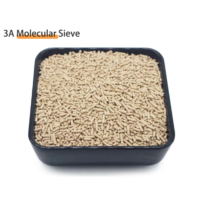
Molecular Sieve 3A / 4A / 5A / 13X / LiLSX
COAs traceable to the specific mesh + binder lot loaded in your bed — every shipment ships with desorption isotherm data so your emergency-discharge source-strength budget uses the actual inventory, not the generic catalog value.
View Product Details →