Emergency Adsorbent Discharge System Design for Toxic Gas Release: Vent Stack Height vs LFL
Adsorber Vessel Internal Corrosion Under Cyclic Regeneration: Crevice Corrosion at Distributor Plate Welds
1. Why Distributor Plate Welds Fail Before the Rest of the Vessel
An adsorber vessel is a shell, two heads, a top inlet nozzle, a bottom outlet nozzle, and a series of internal trays — feed gas distributor at top, optional middle support beam(s), product gas collector at bottom, plus any number of instrument nozzles and thermowells. The distributor at the top of the bed is a perforated plate, vane-type distributor, or chimney-tray design; in every case it is welded to the vessel shell or to a support ring that is welded to the shell. The weld is the structural and corrosion-life weak point.
Three reasons converge at the distributor weld. Geometry: the root gap of any shell-plate weld is a physical crevice by definition, regardless of whether the joint is a single-V, double-V, or J-groove. The gap excludes oxygen from the inside surface and creates the cathode-anode geometry that drives crevice corrosion. Metallurgy: the heat-affected zone (HAZ) of an austenitic stainless-steel weld in 304L or 316L is sensitised — chromium carbide (Cr23C6) precipitates at grain boundaries during the 600-850 °C thermal cycle of arc welding, leaving the grain-boundary region locally depleted in Cr (below the 12 wt% threshold that stabilises the passive film). Service environment: cyclic regeneration concentrates the corrosion driver at the top of the bed. Bed temperature cycles between 30-50 °C (adsorption) and 200-320 °C (regeneration); inlet moistures pass through the bed as steam during regeneration and condense at cold spots during adsorption; any chloride in the feed concentrates in the condensate at the distributor plate and in the weld HAZ. The combination — crevice geometry + sensitised HAZ + chloride-bearing condensate — is the textbook geometry for crevice-passive-cell attack per ASTM G48 Practice B and ASTM G36.
This mode is rarely caught early because it is invisible from outside. The first sign of distress inside is a tiny pinhole leak at the distributor weld, typically 7-15 years into service, that releases adsorbent dust into the regeneration vent and shows up as a step-change in outlet-gas dewpoint or visible dust downstream of the outlet filter. By the time the leak is detected by gas-side monitoring, the HAZ has typically lost 30-60% of its wall thickness. Repair requires unloading the bed, weld overlay or section replacement, post-weld heat treatment, and bed reload — 14-28 days of outage and $200-500k in direct cost.
1.1 The differential aeration cell in detail
The crevice-corrosion mechanism is a differential aeration cell. Inside the crevice (weld root gap, backing strip, distributor plate underside where condensate pools), oxygen is consumed by cathodic reduction of the passive film and is not replenished by diffusion. Outside, the bulk solution is oxygen-saturated. The potential difference drives the anodic dissolution reaction inside the crevice — metal dissolves, releasing Fe2+/Cr3+/Ni2+ into the confined solution. Chloride ion migrates in to balance the charge, dropping the local pH below 2 within hours and accelerating the dissolution. The passive film cannot repassivate because pH is too low; the cell is self-sustaining until perforation.
Initiation time is weeks to months once crevice geometry, sensitised microstructure, and chloride condensate are all present. Propagation rate in chloride-bearing condensate at 50-80 °C in a sensitised 304L HAZ is typically 0.5-2.5 mm/year per ASTM G48 Practice C extrapolation and per field coupon data from NACE SP0775 monitoring. A 12 mm corroded distributor plate (typical for a 1.5 m diameter adsorber operating at 8-15 barg) has roughly 4-8 years of propagation time from initiation to perforation once the cell is established. This is why we see distributor weld failures clustered in the 7-15 year service-life band.
2. The Cyclic-Regeneration Condensation Pattern That Drives the Cell
The condensation pattern at the top of an adsorber bed is driven by three stacked thermal transients. The regeneration cycle heats the bed from 30-50 °C (end of adsorption) to 200-320 °C (peak regeneration) over 30-90 minutes, holds at peak for 60-180 minutes, then cools back to feed temperature over 30-90 minutes. The adsorption cycle wets the bed as feed gas (typically saturated or near-saturated with water at line temperature and pressure) passes through. The bed-to-shell thermal inertia lags the bed-internal temperature by 15-60 minutes during each transition, so the shell at the top of the vessel is always slightly cooler than the bed itself during regeneration and slightly warmer during adsorption.
The transient where the shell is colder than the bed-internal temperature is the critical window. Water vapour condenses on the cold shell and on the underside of the distributor plate. This 'regeneration condensate' carries with it any chloride, sulfide, or organic acid driven off by the regeneration heat. The condensate pools at the distributor-plate underside and in the weld HAZ, sits there through the cool-down, and is the bulk solution that drives the crevice cell. Volume per cycle is small — 1-5 L/m² of distributor area per cycle — but chloride loading is concentrated, often 50-500 ppm Cl- vs 1-10 ppm Cl- in the bulk feed gas moisture.
2.1 The four sources of chloride in the condensate
Chloride in the condensate comes from one of four sources, and the dominant source determines the mitigation strategy.
Source 1 — feed-gas chloride. Natural gas at the wellhead typically carries 50-500 ppmv Cl- as HCl from formation water or completion fluids. The inlet separator removes the bulk liquid but a low-salt aerosol of chloride-bearing water carryover is normal at the 1-5 ppmv Cl- range. This chloride is unavoidable and is the baseline loading on every adsorber. Mitigation is upstream chloride guard bed; useful but expensive intervention discussed in the FAQ.
Source 2 — molecular sieve hydrolysis. Chloride-form 4A molecular sieve (the as-synthesised form, not the more common sodium/potassium form) releases HCl at regeneration temperatures above about 150 °C in the presence of adsorbed water. The reaction is irreversible and chloride is released to the regeneration vent stream and condenses in the cold spots at the top of the vessel. If your sieve supplier provides chloride-form 4A (or worse, chloride-form 13X), the chloride loading on the distributor weld is 5-20x the baseline from feed alone. Specify low-sodium or potassium-form sieve, demand lot-by-lot COA with chloride test method and detection limit, run a one-lot trial as described in the FAQ.
Source 3 — glycol carryover. Upstream glycol dehydration units (TEG, MEG, DEG) carry over low ppms of liquid glycol into the adsorber feed. The glycol itself is not corrosive, but the chloride in the glycol (typically 100-500 ppmw Cl-) is. Mitigation is upstream dry-gas filter coalescer, glycol separation improvement, and inlet-separator upgrade — all capital projects, but typically pay back in 3-5 years on reduced bed-replacement frequency alone.
Source 4 — chloride-bearing wash water. If the operator backwashes the sieve with potable water (during commissioning, after a bed upset, or during hot-N2 regeneration of a sour-gas unit), the chloride in the wash water (50-300 ppmw Cl- in untreated municipal water) is adsorbed and concentrated on the sieve and released on the next regeneration. Mitigation: use demin or condensate water for any sieve backwash; procedural fix with no capital cost.
2.2 The hot-cold spot geometry
The vessel shell at the top is welded to the upper head and is in contact with the regeneration gas at 200-320 °C, but the shell wall mass at the top is large and lags the internal gas temperature by 10-30 °C during the regeneration peak. During cool-down, the shell wall mass cools faster than the bed (it loses heat to ambient through the top-head insulation) and is the coldest point in the vessel for 30-90 minutes. This is where regeneration condensate pools — on the underside of the top head and on the underside of the distributor plate. Mitigation: insulate the entire vessel including the top head and the bottom head, not just the cylindrical shell. Operators who have already insulated the heads consistently report a 3-5x reduction in regeneration-condensate volume at the distributor.
3. Screening Tests for Distributor Weld Crevice Susceptibility
Five ASTM standards cover the screening of alloy susceptibility to crevice corrosion in chloride environments, plus ASTM A380 covers passivation. Knowing which test to run and how to interpret the result is the difference between catching the problem at a planned outage and an unscheduled shutdown.
ASTM A262 Practice A (oxalic acid etch). The cheapest screening test, used to detect chromium-depletion sensitisation in austenitic stainless steel. A sample is electropolished, etched in 10% oxalic acid at 1 A/cm² for 90 seconds, and examined at 100-500x magnification. The etch structure classifies the microstructure as 'step' (unsensitised), 'dual' (slightly sensitised), or 'ditch' (fully sensitised). Dual and ditch are unacceptable for cyclic chloride service. Cost: $100-300 per sample, 1-3 days turnaround. Run this on every new WPS or field repair weld first.
ASTM A262 Practice B (Streicher test). Quantifies the intergranular corrosion rate by mass loss in boiling ferric sulfate + 50% sulfuric acid for 120 hours. Mass-loss rate correlates with chromium-depletion depth and predicts susceptibility to intergranular attack. Cost: $300-800, 5-7 days.
ASTM A262 Practice E (Strauss test). A bend-test version — sample is exposed to copper-sulfate-sulfuric acid solution for 720 hours, then examined for cracks after bending. Cracks confirm sensitisation. Cost: $400-800, 30 days. Tiebreaker when Practice A and B disagree.
ASTM G48 Practice B (ferric chloride pitting-crevice, 22 °C). Standard pitting and crevice test. Samples with crevice assemblies per Figure 1 of G48 are exposed to 6% FeCl3 at 22 °C for 72 hours, then examined for pitting and crevice attack. The critical crevice temperature (CCT) and critical pitting temperature (CPT) can be determined by running at a series. Cost: $200-500, 4-7 days. Run this on every alloy alternative before committing to a material change.
ASTM G48 Practice C (controlled temperature). Rate-quantifying version of Practice B. Samples are exposed at 4-6 temperatures, mass loss plotted vs 1/T in Kelvin, rate extrapolated to service temperature. Cost: $600-1500, 14-21 days. Run only on the final candidate alloy.
ASTM G36 (boiling MgCl2 stress-corrosion cracking). Constant-strain bent-beam test in boiling 155-172 °C 45% MgCl2. Ranks alloy susceptibility to chloride SCC. Cost: $400-800, 5-10 days.
NACE TM0174 / ISO 22479 (cyclic potentiodynamic polarisation). Electrochemical test that derives pitting and repassivation potentials. The difference is a quantitative measure of crevice-corrosion resistance. Cost: $500-1000, 3-7 days. Most reliable single test for cyclic chloride-condensate service; run in addition to ASTM G48 for critical alloy decisions.
For a typical field repair decision (316L + Alloy 625 overlay vs 316L with new WPS vs duplex 2205), the screening sequence is: ASTM A262 Practice A on every weld-overlay coupon to confirm WPS controls sensitisation, ASTM G48 Practice B at three temperatures on every alloy candidate to bracket the CCT, ASTM A380 on every field-welded joint to confirm passivation. Total test programme: $2000-4000 and 4-6 weeks. The marginal cost is dwarfed by the $200-500k cost of an unscheduled repair if the wrong alloy or WPS is selected.
4. Field-Applicable Mitigation Options
Mitigation options for an existing distributor weld crevice problem fall into four categories. The right choice depends on the inspection findings, planned outage schedule, budget, and tolerance for future unscheduled repair.
4.1 Post-weld solution annealing (the gold standard, hard to apply field)
Solution annealing at 1050-1100 °C followed by water quench dissolves the chromium carbides precipitated in the HAZ during welding and re-homogenises the Cr distribution. The HAZ microstructure returns to the unsensitised step structure per ASTM A262 Practice A. For new vessels built at the OEM fabricator, this is routine and adds essentially zero cost. For field-installed vessels, solution annealing requires shutting down the unit, removing the bed, cleaning the vessel internally, wrapping the entire vessel in temporary insulation, installing temporary gas burners, ramping to 1050-1100 °C at ≤100 °C/h with controlled atmosphere, holding for 1-2 hours per inch of wall thickness, then water-quenching. The temporary insulation and gas-burners installation is 4-6 weeks of field work; the heat treatment cycle is 36-48 hours; the cost is $300-800k. For most operators, solution annealing of a field-installed vessel is uneconomic — the cost approaches half the cost of a new vessel. The mitigation is most often used for new vessels or for major shop repairs where the vessel is removed from service and shipped back to a fabricator with a furnace.
4.2 Alloy 625 weld overlay (the workhorse field mitigation)
Alloy 625 (UNS N06625, nominal Ni-62, Cr-22, Mo-9, Nb-3.5) has PREN ≈ 50 and is essentially immune to chloride crevice corrosion up to about 80-100 °C in cyclic condensate service. Depositing Alloy 625 over a 304L or 316L weld HAZ isolates the sensitised microstructure from the condensate. The weld overlay procedure must control parent-metal dilution to <30% (stringer beads, heat input ≤1.0 kJ/mm, cold-wire feed, two or more overlay passes to push the diluted first pass into the parent), deposit a chemically-pure Alloy 625 cap (verified by NACE MR0175 / ISO 15156 chemistry check), and be qualified to ASME Section IX plus NACE MR0175 for the worst-case chloride/H2S combination. Field application cost is $50-150k per distributor weld overlay; outage is 3-7 days per distributor; expected service life is 15-25 years in cyclic chloride-condensate service.
4.3 Electropolishing (surface treatment)
Electropolishing removes the rough, Cr-depleted outermost layer of the weld HAZ and replaces it with a smooth, Cr-enriched passive film. Surface roughness drops from Ra ≈ 0.8-3.2 µm (typical as-welded) to Ra ≤ 0.25 µm (electropolished), reducing crevice formation on the surface and removing the most-depleted layer. For new vessels or vessels returning to a shop for repair, electropolishing is routine. For field-installed vessels, electropolishing is feasible but expensive: the vessel is filled with an electrolyte (typically phosphoric-sulfuric acid blend), a cathode is inserted, and DC current is applied for 5-15 minutes per m² of internal surface. Cost is $30-80k for a 5-15 m³ vessel and downtime is 1-3 days. Electropolishing is most often used in combination with Alloy 625 overlay (overlay the weld HAZ, electropolish the entire internal surface).
4.4 Nitrogen purge cooldown (the procedural mitigation, zero capital cost)
During cool-down, the bed temperature crosses the feed-water dew point at 50-80 °C. Below this, the water vapour in the bed condenses on the cold metal — shell, distributor plate, thermowells. If the cool-down is done under feed-gas flow, the condensate volume is high. If the cool-down is done under nitrogen purge (dry), the condensate volume is minimal — only residual adsorbed water from regeneration dry-down is left to condense, and most stays on the molecular sieve rather than on the metal. Implementing nitrogen-purge cooldown requires a nitrogen supply at the regeneration vent (typically 30-60 Nm³/h liquid-nitrogen or an N2 generator), a valve-hold sequence in the control logic, and operator training. Cost is essentially zero for operators who already have regeneration-grade nitrogen available, and $50-150k for operators who need to install the supply. Operators who have implemented this consistently report a 5-10x reduction in regeneration-condensate volume and a corresponding 5-10x extension of distributor weld service life.
4.5 Top and bottom head insulation
The top and bottom heads of an adsorber are typically uninsulated. Their thermal mass creates the hot-cold spot geometry that drives regeneration condensate pooling at the distributor. Insulating the heads with high-temperature calcium-silicate or mineral-wool blanket (50-100 mm thickness, vapor barrier, stainless-steel weather jacket) costs $20-50k per vessel and 5-10 days of outage work. Same payback as nitrogen purge: 5-10x reduction in regeneration-condensate volume and corresponding extension of distributor weld life. Most operators implement both interventions together at the next planned outage at a combined cost of $50-200k with payback of 18-36 months on the avoided repair cost alone.
| Mitigation | Cost | Outage | Service-life extension | When to use |
|---|---|---|---|---|
| Post-weld solution anneal | $300-800k | 4-6 weeks | 20-30 years | New vessels or shop repair |
| Alloy 625 weld overlay | $50-150k | 3-7 days | 15-25 years | Field repair, localised attack |
| Electropolish | $30-80k | 1-3 days | 10-15 years | Combination with overlay |
| N2 purge cooldown | $0-150k | 2-5 days | 5-10x life extension | Always if N2 available |
| Head insulation | $20-50k/vessel | 5-10 days | 5-10x life extension | Always at next planned outage |
Table 1 — Mitigation options ranked by cost and service-life extension. The procedural interventions (N2 purge + head insulation) are the highest-payback-to-lowest-cost interventions and should be implemented first; the capital interventions (anneal, overlay, electropolish) are layered on top depending on inspection findings.
5. The In-Service Inspection Programme That Catches Crevice Before Perforation
Standard ASME Section VIII fabrication inspection ends at the factory. For cyclic-regeneration adsorbers in chloride-bearing feed, this is insufficient. The minimum in-service inspection programme is a 5-year borescope + 10-year phased-array UT + 2-year coupon retrieval, scheduled into planned outages to minimise incremental downtime. The programme consistently catches distributor-weld crevice 4-8 years before perforation would have occurred, with planned-repair cost of $80-200k vs unscheduled-repair cost of $300-800k.
| Inspection | Frequency | Outage | Cost/vessel | Output |
|---|---|---|---|---|
| Borescope | 5 years | 2-3 days, top bed removed | $10-30k | Photo log, qualitative |
| Phased-array UT | 10 years | 7-14 days, bed removed | $30-60k | Wall-thickness map, quantitative |
| Coupon retrieval (ASTM G4 / NACE SP0775) | 2 years | 1 day, no bed removal | $3-5k/retrieval | mm/year rate, quantitative |
| Dye-penetrant of suspect areas | After borescope flag | 0.5 day | $2-5k/area | Surface-breaking cracks |
5.1 Borescope inspection
Borescope access requires the vessel depressurised and the top 0.5-1 m of bed removed. A qualified inspector photographs every distributor weld, every thermowell weld, every nozzle weld, and the underside of the top head. Surface oxide, crevice corrosion stains, pitting, and visible cracks are noted. Borescope is qualitative — it detects crevice corrosion only after the crevice has propagated to the visible surface (typically 30-50% wall loss for a 10-15 mm wall). Cost: $10-30k for a 2-3 day campaign, depending on whether the vessel has to be entered or whether a robotic crawler can be used through a 50-100 mm access nozzle.
5.2 Phased-array UT
Phased-array ultrasonic testing detects wall loss below the surface by measuring ultrasonic-pulse time-of-flight through the wall. For a 10-15 mm corroded distributor plate, phased-array UT detects and quantifies wall loss to within ±0.5 mm and identifies the shape and extent of the corroded area — typically 4-8 years of propagation time remain between the first phased-array UT detection of significant wall loss (>20% wall loss) and the perforation point. Phased-array UT on distributor welds typically requires the bed removed and the vessel inside grit-blasted to bare metal, so this is a 7-14 day outage event — schedule with the next major bed changeout. Cost: $30-60k for a 4-bed PSA. Phased-array UT is also a one-time opportunity to baseline the as-fabricated wall thickness for future comparison.
5.3 ASTM G4 coupon monitoring per NACE SP0775
Coupon monitoring is the workhorse of in-service corrosion rate measurement. Three coupon racks per vessel — one at the top (above the bed), one at mid-bed, one at the bottom. Each rack holds 4-6 coupons of the same alloy as the vessel plus coupons of any candidate alloy alternative. Retrieved at every 2-year planned outage, weighed, photographed, and analysed for mass loss and corrosion mode. ASTM G1 calculation translates coupon mass loss to mm/year with no extrapolation. Cost: $5-10k per rack fabrication + $3-5k per retrieval-and-analysis cycle. Over a 20-year service life, $50-100k per vessel.
For the broader cost-vs-benefit picture of inspection programmes on adsorber vessels, see our companion piece on API 521 depressurization vent sizing for adsorber vessels. The cryogenic variant of the same approach — applicable to liquefied-hydrogen and LNG adsorbers — is covered in ISO 23251 cryogenic adsorber piping stress analysis.
6. The Repair vs Replace Decision Matrix
When borescope and phased-array UT confirm significant distributor weld crevice attack (typically >30% wall loss over >20% of the weld length, or any localised pitting >50% wall loss), the operator must choose between weld repair and full material upgrade. The decision depends on the outage schedule, horizon planning, and tolerance for unscheduled repair.
6.1 Weld overlay on the localised weld ($50-150k per weld, 3-7 day outage)
For localised attack (one weld, <30% wall loss), Alloy 625 weld overlay is the typical repair. Grit-blast the affected weld and 50-100 mm of surrounding parent metal to white metal, deposit Alloy 625 overlay with the controlled WPS from §4.2, qualify with ASTM A262 Practice A on a coupon, hydrostatically test the vessel after the overlay, return to service. Expected service life of the repair is 15-25 years in cyclic chloride-condensate service. Appropriate when the localised attack is the only significant inspection finding, the vessel has ≥15 years of remaining service life in the operator's planning horizon, and the operator has a planned outage window in the next 6-12 months. NOT appropriate when the inspection reveals multiple welds with significant attack, or when attack has progressed to perforation.
6.2 Section replacement ($200-500k per weld, 14-28 day outage)
For advanced attack (50-80% wall loss) or perforation, the distributor plate or shell section containing the weld must be cut out and replaced. Grit-blast, cut out the corroded section, machine a new section (316L or 254 SMO plate stock), weld in with the qualified WPS, post-weld heat treat if practical (rarely practical for field repair), hydrostatic test, return to service. Appropriate when attack has progressed to perforation or near-perforation, the affected weld is in a geometrically critical location, or the operator wants to upgrade the local alloy at the same time. Section replacement is NOT appropriate as a planned intervention — only as a response to an inspection finding or a leak.
6.3 Full material upgrade to duplex 2205 or 254 SMO ($1.5-3M per vessel, 9-15 month project)
For vessels with multiple welds in significant attack, or vessels approaching end of planning horizon with a known corrosion problem, full material upgrade is the brute-force intervention. The vessel is replaced with a new vessel built from duplex 2205 (UNS S32205) or super-austenitic 254 SMO (UNS S31254), both essentially immune to chloride crevice corrosion in cyclic-condensate service up to 80-100 °C and 100-120 °C respectively. The new vessel is fabricated at the OEM shop with full ASME Section VIII / ASME B31.3 qualification, solution-annealed at 1050-1100 °C, hydrostatically tested, shipped, installed. Cost: $1.5-3M per vessel; lead time: 16-26 weeks for plate + 12-20 weeks fabrication + 4-8 weeks shipping and installation. Total project: 9-15 months from order to commissioning. Appropriate when multiple welds across multiple beds show significant attack, the vessel has <10 years of remaining service life AND the cost of three full weld repairs over the remaining life would exceed the upgrade cost, or the operator is doing a major capacity expansion requiring a new vessel. NOT appropriate for localised findings with ≥15 years of remaining life — weld overlay is more cost-effective.
The economic crossover for full material upgrade vs repeated weld-overlay repair is roughly: if you would otherwise need three full distributor-weld repairs over a 30-year vessel life, a duplex or super-austenitic vessel built once is cheaper. For most operators running 10-15 year horizon planning with one mid-life repair, the 316L + Alloy 625 overlay + chloride-management path is more economic. Get a life-cycle cost (LCC) model from your fabricator before deciding.
6.4 Decision checklist
Use this 5-point checklist at the next planned outage to decide between repair and replace:
- Inspection finding: how many welds show significant attack? (1 = overlay; 2-3 = overlay + procedural + sieve QC; >3 = consider full upgrade)
- Wall loss at worst location: <50% = overlay; 50-80% = section replacement; >80% or perforation = emergency section replacement
- Operator planning horizon: <10 years remaining = upgrade; 10-15 years = overlay if localised, upgrade if multi-weld; >15 years = overlay + procedural
- Feed chloride trajectory: increasing over time = upgrade; stable at <5 ppmv = overlay; stable at 5-20 ppmv = overlay + guard bed; ≥20 ppmv = upgrade
- Sieve chloride specification: low-sodium / potassium-form with lot COA = supportive of overlay; chloride-form sieve = upgrade
For a more detailed economic decision framework on adsorber vessel lifecycle cost, see our companion piece on vessel cleaning cost vs bed replacement decision. The complementary angle on discharge-system design for cyclic-regeneration adsorbers is covered in emergency adsorbent discharge vent stack height vs LFL.
7. Field Case Study — 8-Year Distributor Weld Failure on a Natural Gas PSA
The case study is a 10-bed natural-gas PSA dehydration unit, commissioned 2017, 304L stainless construction, 2.0 m diameter × 8 m tangent-to-tangent, 12 mm corroded shell, designed for 12 barg operating pressure, 4A molecular sieve (sodium form, 1.6-2.5 mm particle size, COA chloride <500 ppmw from vendor), regeneration at 230 °C with feed-gas cooldown (nitrogen-purge cooldown not implemented), upstream inlet separator in service. Feed chloride baseline 5 ppmv.
After 6 years of service (2023), a planned outage for bed changeout allowed a borescope inspection of all 10 distributor welds. Findings: 7 of 10 distributor welds showed visible crevice attack at the root pass, with wall loss 20-40% over 30-60% of the weld length; the worst case (Bed 4) showed 50% wall loss with visible perforation weeping. The ceramic-fibre permanent backing strip had been left in place on all 10 distributor welds — the OEM fabrication procedure did not require back-gouging and root-pass grinding.
The operator's response was phased. In 2024 (Beds 4 and 6 only, most affected), full section replacement of the distributor-to-shell weld region with 316L plate, with back-gouging and root-pass grinding to remove the backing strip, followed by Alloy 625 weld overlay on the HAZ. Cost: $280k per section × 2 = $560k. In 2026, nitrogen-purge cooldown ($80k, existing nitrogen available) + top/bottom head insulation ($35k/vessel × 10 = $350k). Total mitigation: $990k + $80k inspection/engineering = $1.07M. Compared to the alternative of waiting for unscheduled failures ($120k/day loss-of-production + $300-500k per unscheduled repair, total expected $2-3M), the phased mitigation breaks even by avoiding the second unscheduled failure and is solidly economic if it avoids both. The operator has now standardised on: 316L + Alloy 625 overlay for future vessel repairs, nitrogen-purge cooldown, top-and-bottom head insulation, low-sodium sieve with lot-by-lot COA, and the 5-year borescope + 10-year phased-array UT inspection programme.
8. What to Demand from Your Adsorbent Vendor and Vessel Fabricator
Three specifications that operators consistently get wrong on the procurement side, and the corrections:
Sieve specification. Specify low-sodium potassium-form 4A (or sodium-form with lot-by-lot COA showing <200 ppmw Cl-) or specify 13X with the same lot-by-lot COA requirement. Reject any 'as-synthesised' chloride-form sieve. Demand the test method and detection limit on the COA — a chloride spec without a test method is meaningless. For sour-gas units, specify NACE MR0175 / ISO 15156 compliance on the sieve as well as the vessel, since the sieve can introduce chloride that drives downstream corrosion. The detailed sieve QC specification (acceptance criteria, sampling per ANSI/ASQ Z1.4, screening-test methodology) is covered in our spent molecular sieve moisture/LOI methodology guide.
Fabricator WPS qualification. Demand ASME Section IX qualification PLUS an ASTM A262 Practice A test result on the actual WPS to be used for the distributor-to-shell weld. A dual or ditch structure is unacceptable for cyclic chloride service. Demand ferrite number ≤4 on the weld cap (Ferro Number per ASTM A800 or magnetic ferroscope), confirmed on a production weld coupon. Demand backing-strip removal and back-gouging on every distributor weld, with no exceptions for 'as-built is fine' rationalisations.
Fabricator passivation. Demand ASTM A380 passivation of the entire internal surface after fabrication and before shipment. The standard pickle-and-passivate with nitric + hydrofluoric acid blend followed by nitric acid passivation produces the corrosion-resistant surface that the alloy chemistry promises. A vessel that ships without ASTM A380 passivation is operating with a degraded surface from day one and will fail earlier than the alloy chemistry predicts.
The complementary upstream-side procurement specification — molecular sieve particle size distribution and fines-content limits, which directly affect adsorber pressure drop and bed life — is covered in our ISO 13320 vs ASTM D4464 sieve method comparison.
For the full AluminaWorld product range relevant to adsorber vessel fabrication and operation: activated alumina for chloride-scavenging guard beds, alumina powder for high-packing-density bed support layers, aluminum hydroxide (ATH) for refractory lining formulations, and ZSM-5 zeolite for chloride-tolerant catalyst support alternatives where molecular sieve is not viable.
10. Frequently Asked Questions
Why does crevice corrosion preferentially attack the weld HAZ at the distributor plate rather than the parent metal of the shell?
Two reasons. First, the weld heat-affected zone (HAZ) is a metallurgical discontinuity where chromium carbide (Cr23C6) precipitates at grain boundaries, leaving the grain-boundary region locally depleted in Cr (below the 12% threshold that stabilises the passive film). Second, the distributor-to-shell geometry creates a physical crevice that traps regenerator-vent condensate and excludes oxygen. Sensitised microstructure + oxygen-starved crevice + chloride-bearing condensate is the textbook geometry for crevice-passive-cell attack per ASTM G48 Practice B and ASTM G36.
We operate a 304L vessel on natural-gas PSA dehydration. Operator log shows 'light surface oxide' after 6 years. Is that a corrosion flag or normal aging?
It depends on where the oxide is. Uniform light oxide across the entire internal shell after 6 years is normal aging in low-chloride feed (<5 ppmv Cl-) — passive film renewal from trace O2 ingress, no action needed. But if the oxide is concentrated at the distributor weld seams, in a ring around any thermowell or nozzle weld, at the bottom of the vessel where condensed water pools, or on the inside of any unground backing strip, it is the precursor to pitting and crevice attack. Take a borescope photo and a chloride swab (ASTM D512 or ASTM D4329 IC) of any pooled water. If local Cl- exceeds 50 ppm in the pooled water and the oxide is at a weld, you are one thermal cycle away from a leak.
Our HAZ microstructure showed 'dual' (ferrite-austenite) after weld qualification, but the welding procedure said 'fully austenitic'. Is dual acceptable?
For cyclic regeneration in chloride-bearing feed, dual microstructure is a problem, not a cosmetic issue. Ferrite phase in an austenitic matrix preferentially attacks in reducing-acid chloride environments. The ferrite-austenite interface is also a preferred path for stress-corrosion cracking under sustained tensile residual stress from weld shrinkage. ASME Section IX qualification does NOT cover cyclic-chloride service specifically — that requires separate qualification per ASME B31.3 §A330 or per NACE MR0175 / ISO 15156. For cyclic PSA with 50-200 ppmv Cl- in feed, specify a fully austenitic 308L/309LMo overmatch filler and limit ferrite to FN ≤ 4 per ASTM A800.
What is the actual service-life penalty of leaving the ceramic-fibre permanent backing strip in the distributor-to-shell weld?
If the backing strip is the standard ceramic-fibre type, it is hygroscopic and chloride-bearing within 6-12 months of service. Combined with the oxygen-starved crevice geometry it creates, the backing-strip interface becomes a permanent chloride reservoir that fuels sustained crevice corrosion for the life of the vessel. We have seen vessels fail at the backing-strip interface at 7-11 years of service where the equivalent weld geometry without backing strip would have reached 18-22 years. Fix: back-gouge the root from the inside after first-side welding, grind out the backing strip completely, then weld the second side from the inside with full penetration under argon purge.
We see condensate at the bottom of the bed after every regeneration. Is this normal?
Condensate at the bed bottom is normal during the cool-down step (the bed temperature crosses the feed-water dew point as it cools from 200-250 °C regeneration to 30-50 °C feed), but volume and chloride loading matter. Normal: 1-3 L/m² of bed cross-section per cycle, with Cl- <10 ppm. Abnormal: >5 L/m²/cycle, Cl- >50 ppm, or any visible iron oxide tint. Abnormal condensate indicates insufficient regeneration dry-down, feed-gas saturation, molecular sieve hydrolysis, or hot-cold spot in the vessel shell below the distributor (insulate the lower 1/3 including the bottom head).
Is ASTM G48 Practice B (ferric chloride pitting) really predictive of in-service crevice corrosion, or is it a lab-only screen?
ASTM G48 Practice B (6% FeCl3, 22 °C, 72 h, crevice assembly per Figure 1) is a screening test, not a service-life predictor. A pass says the alloy is NOT susceptible to crevice initiation in the most aggressive chloride environment the test simulates. A fail says the alloy WILL crevice-corrode in that environment. The test does not predict rate or service life. For service-life prediction, use ASTM G48 Practice C (log-linear extrapolation of mass loss vs 1/T to estimate service exposure) or NACE TM0174 / ISO 22479 cyclic potentiodynamic polarisation. For actual in-service rate, deploy ASTM G4 coupon racks per NACE SP0775 at three positions in the vessel and weigh at every outage.
We have done four Alloy 625 weld-overlay repairs in the field. None of them have failed in 6 years. Is overlay always the right call?
Alloy 625 weld overlay typically survives 15-25 years in cyclic chloride-condensate service, consistent with your 6-year field experience. The risk is in the welding procedure. For overlay to work without a post-weld anneal, the WPS must: (a) limit parent-metal dilution to ≤30% (stringer beads, heat input ≤1.0 kJ/mm, cold-wire feed), (b) deposit at least two overlay passes to push the diluted first pass into the parent, and (c) qualify per ASME Section IX AND NACE MR0175 / ISO 15156 for the worst-case sour-service combination, with ferrite ≤1, hardness ≤22 HRC, max interpass 150 °C.
Our molecular sieve vendor supplies 'low-chloride' 13X. What does low-chloride actually mean in ppm?
There is no industry-wide definition. Internal specs are usually <500 ppmw Cl- on a dry-basis test. For 304L adsorber service in PSA natural gas dehydration where feed chloride is <5 ppmv, sieve chloride at <200 ppmw is the practical floor; 200-500 ppmw is acceptable for short-cycle (4-8 year) bed life; >500 ppmw is not acceptable for 304L even with perfect condensate management. The chloride release mechanism is hydrolysis of residual chloride-form 4A at regeneration temperature (>150 °C in the presence of adsorbed water releases HCl). If your vendor cannot certify <200 ppmw Cl- on a lot-by-lot COA with the actual test method and detection limit, run a one-lot trial.
We do NDE only at the OEM fabrication shop, never in-service. Is in-service NDE worth the outage?
For cyclic-regeneration adsorbers in chloride-bearing feed: yes. The marginal cost of one in-service borescope + one phased-array UT scan at the 5-year planned outage is a tiny fraction of the cost of an unscheduled shutdown from a leaking distributor weld (typical loss-of-production $50-500k per day for a 100-tpd hydrogen unit, plus the cost of a hot emergency-repair weld). Minimum NDE programme: borescope every 5 years, phased-array UT every 10 years, coupon rack every 2 years, dye-penetrant of any suspect area.
Does upstream chloride scavenging (e.g., a chloride guard bed) eliminate the risk or just move it?
It moves the risk, it does not eliminate it. A chloride guard bed (4A at 1-2 tonnes, 6-12 months service, operated at 30-50 °C upstream) captures the bulk of the feed chloride but becomes a concentrated chloride reservoir at end-of-life. Spent guard-bed disposal then becomes the chloride-handling problem. In practice you gain 5-10 years of main-bed life at the cost of managing a new waste stream. Economic if the alternative is an unscheduled weld repair; less so if the alternative is a planned inspection programme with mitigation.
What about upgrading the vessel material entirely to duplex 2205 or super-austenitic 254 SMO?
Duplex 2205 (UNS S32205, PREN ≈ 35) is essentially immune to chloride crevice corrosion up to ~80-100 °C — well above any PSA/TSA bed-temperature profile. 254 SMO (UNS S31254, PREN ≈ 43) is good to ~120 °C. But: 4-8x cost per kg of plate, limited domestic fabrication shops (welding requires nickel-rich fillers, strict heat-input control, no post-weld anneal in most shops), and 16-26 week plate procurement. Economic crossover is roughly: if you would otherwise need three full distributor-weld repairs over a 30-year vessel life, duplex or super-austenitic built once is cheaper. For 10-15 year horizon with one mid-life repair, 316L + Alloy 625 overlay + chloride management is more economic.
11. Next Steps — Spec, Test, Inspect
If designing a new cyclic-regeneration adsorber: specify duplex 2205 or 254 SMO for the distributor and upper 1 m of shell, demand ASME Section IX WPS qualification plus ASTM A262 Practice A on a production weld coupon, demand backing-strip removal with back-gouging, demand ASTM A380 passivation, demand the 5-year borescope + 10-year phased-array UT inspection programme from day one. Incremental cost vs 304L + field-overlay is $200-400k per vessel; savings over 30 years are $1-3M per vessel in avoided repair.
If operating an existing 304L/316L adsorber in chloride-bearing feed: run a one-lot sieve trial with lot-by-lot COA showing <200 ppmw Cl-, implement nitrogen-purge cooldown (lowest-cost highest-payback), insulate top and bottom heads, install ASTM G4 coupon rack per NACE SP0775, schedule the 5-year borescope into the next planned outage. Total programme over 3-5 years: $200-400k per vessel; payback is the avoided cost of one unscheduled repair.
If facing a confirmed distributor-weld crevice failure: get the phased-array UT map, calculate remaining wall at the worst-case location, schedule weld overlay on the most affected welds at the next planned outage (procedure in §4.2). If inspection reveals multiple welds with significant attack, run the full material upgrade LCC model from your engineering contractor and compare to the cost of three full weld repairs over the remaining vessel life.
Get a sieve specification review and chloride-loading analysis for your adsorber. Send us your feed composition, operating pressure and temperature, current sieve specification, and last bed-replacement date. We return a sieve chloride spec, a sieve-grade scope statement, and an inspection-programme recommendation within 4-7 working days, free of charge.
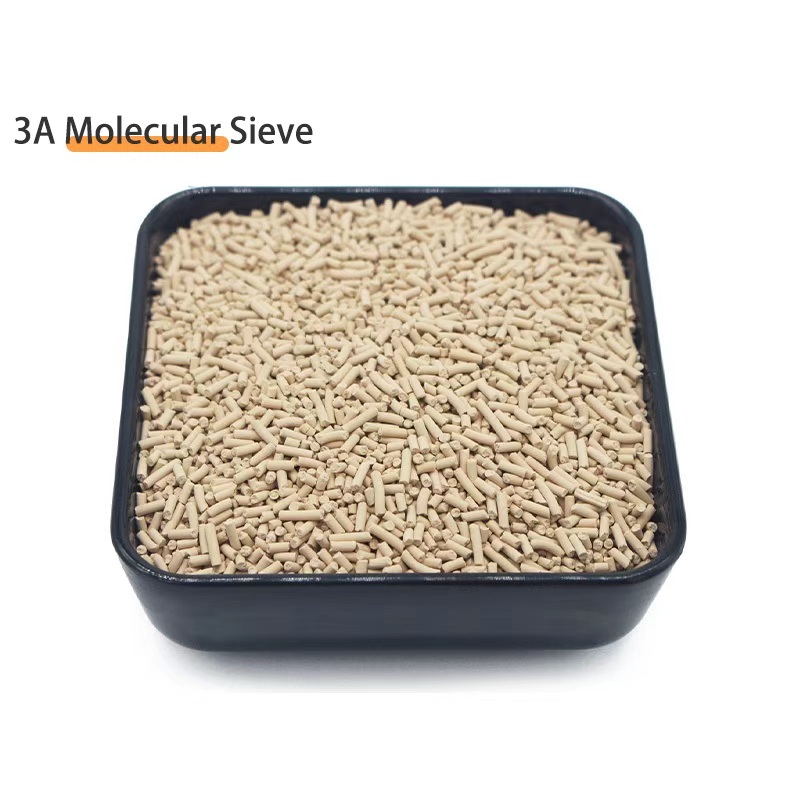
Molecular Sieve 4A / 13X — Low-Sodium Potassium-Form, Lot-by-Lot COA
Low-chloride potassium-form 4A and 13X molecular sieve with lot-by-lot chloride test on the COA (typically <200 ppmw Cl-), reducing the hydrolysis-released HCl that drives distributor weld crevice corrosion in cyclic-regeneration service.
View Product Details →