Pellet Diameter vs Bed Pressure Drop: Why the 4x6 Mesh vs 8x12 Mesh Trade-Off Is More Complicated Than Vendor Tables Suggest
Primary reader: process engineer or procurement engineer who has to choose between two size fractions of the same adsorbent and defend the choice to someone who is only looking at the price per kilogram. Nearly every granular adsorbent supplier publishes a particle size distribution and a bulk density, and nearly every one of them also publishes a “pressure drop” figure or lets you infer one from a curve. Those tables are not wrong, but they answer a narrower question than the one you are actually asking, and the gap between the two is where the expensive mistakes live. Moving from 4x6 mesh to 8x12 mesh does not simply mean “more fines, more pressure drop”. It changes which physical term dominates the pressure drop, how much adsorbent the vessel holds, how fast the bed transmits heat and mass, and how quickly it generates dust in service.
The core problem is that pressure drop in a packed bed is not a property of particle diameter alone. It is a property of diameter, void fraction, shape, size distribution, gas density, gas viscosity and the superficial velocity the bed actually sees. A table listing “4x6 mesh: 25 mbar/m” and “8x12 mesh: 60 mbar/m” for one gas and one velocity has silently assumed the other seven variables, and is valid only for the gas, velocity and packing it was computed on. This guide builds the comparison from the governing equation, works through the variables that most often invalidate a vendor number, and ends with clause language that makes it defensible in a purchase agreement.
The Question a Vendor Particle-Size Table Cannot Answer
A buyer comparing two grades of molecular sieve usually arrives with a spreadsheet and two questions. The first is straightforward: which grade gives more working capacity per cubic metre of vessel? The second is the one that generates the disputes: will the smaller grade push my bed differential pressure past what my blower can deliver, and will it do that from day one or after six months in service?
Answering the first requires only bulk density, because capacity per vessel volume is working capacity per unit mass multiplied by bulk density. Answering the second means solving a flow problem through a packed bed, and the answer is not a material constant. Raise the inlet gas temperature by 30 °C and the gas viscosity changes by roughly 8 %, changing the viscous term directly. Double the bed velocity and the balance between the two governing terms can change completely. Replace spherical pellets with extruded shapes of the same nominal diameter and the pressure drop can rise by 50 % without any change to the mesh designation.
A further complication appears once the bed is running: fines generation. The pressure drop of a freshly loaded bed is not the pressure drop of the same bed after six months of cyclic service, because the size distribution is changing. Small particles fall into the voids between larger ones and partially re-compact the bed, lowering void fraction and pressure drop; but if the fines are carried out instead, the top of the bed becomes more open while the fines that remain create a finer filter layer on the support. Which behaviour dominates depends on the mechanical strength of the media, the flow direction and whether there is an upstream filter. A grade that starts 40 % lower can end up higher than the coarser grade simply because it produced more fines first. The mechanical behaviour under service loading is covered in the comparison of bulk crush strength and attrition index.
The practical consequence is that a size-fraction decision should be made on a calculation that you can audit, using your own gas properties and your own bed geometry, and then confirmed against the supplier with a matching test condition. It should not be made by reading a number off a table whose assumptions are unstated. The rest of this guide builds that calculation.
What “4x6 Mesh” and “8x12 Mesh” Actually Mean: A Range, Not a Diameter
First, what the mesh designation refers to. In the ASTM E11 / ISO 3310 sieve series used for adsorbent particle size analysis, a mesh number is the number of sieve openings per linear inch, and the corresponding opening is specified in millimetres. The designations 4x6 and 8x12 are size fractions: they specify the two sieves that bracket the product, so a nominal 4x6 mesh product passes the 6 mesh screen and is retained on the 4 mesh screen. The diameters in that fraction are a band, not a single number.
For the calculation below, the representative diameters used are 3.5 mm for the 4x6 fraction and 2.0 mm for 8x12, reasonable mid-band values. A real 4x6 fraction also contains particles of 4.75 mm and 3.35 mm, and the larger particles change the effective packing behaviour. That is why the ASTM D4365 laser-diffraction particle size distribution method exists, and why a specification naming only a mesh fraction leaves room for supplier and buyer to interpret the same words differently.
| Property | 4x6 mesh fraction | 8x12 mesh fraction |
|---|---|---|
| Retained on / passes | 4 mesh (4.75 mm) / 6 mesh (3.35 mm) | 8 mesh (2.36 mm) / 12 mesh (1.70 mm) |
| Representative diameter used | 3.5 mm | 2.0 mm |
| Typical bulk density, molecular sieve (industry range) | 0.62 - 0.66 kg/L | 0.66 - 0.71 kg/L |
| Poured bed void fraction, spheres (industry range) | 0.40 - 0.44 | 0.39 - 0.43 |
| Working capacity per unit mass | Essentially unchanged | Essentially unchanged |
| Working capacity per unit vessel volume | Lower (less mass per m³) | Higher (more mass per m³) |
| Relative pressure drop at the same velocity | Lower | Higher |
The last two rows of that table are worth reading twice. Working capacity per kilogram is a material property set by pore volume and pore distribution, and changes very little between size fractions of the same product. Working capacity per cubic metre of vessel is an installation property set by bulk density. So the smaller fraction genuinely gives more capacity in a given vessel, often the decisive argument in its favour, because vessel capital cost is frequently the largest item on an adsorbent project.
The counter-argument is that the pressure drop penalty and the mechanical robustness penalty arrive together. A smaller particle has a higher surface-area-to-volume ratio, so the same mass of media presents more area to the gas, and it is more susceptible to attrition and dust generation. Choosing the fine fraction means accepting both the blower cost and the dust risk, so the choice is a trade against both rather than a pure optimisation.
The Ergun Equation: Two Terms, Two Regimes
For gas flow through a packed bed of particles, the standard semi-empirical relation is the Ergun equation, published in 1952 and still the basis of essentially all packed-bed pressure drop calculations in adsorption, catalysis and fluidised bed design. The total pressure gradient is the sum of two contributions:
ΔP/L = 150 · μ · (1 − ε)2 · v / dp² + 1.75 · (1 − ε) · ρ · v² / dp
where ΔP/L is the pressure gradient in pascals per metre of bed, μ the gas dynamic viscosity in pascal-seconds, ε the bed void fraction, ρ the gas density, v the superficial (empty-column) velocity in metres per second, and dp the effective particle diameter in metres. The first term is the viscous term, dominated by wall friction and lubrication between particles, and it scales with the first power of velocity. The second is the inertial term, dominated by form drag and particle wake turbulence, and it scales with the square of velocity.
Two structural facts follow from the equation and they drive the whole trade-off. First, both terms depend on diameter in the inverse power: halving the diameter multiplies the viscous term by four and the inertial term by eight. Second, the terms have different velocity exponents, so the mix between them changes with flow rate. At low flow the viscous term dominates and the pressure drop grows roughly linearly with velocity; at high flow the inertial term dominates and it grows with the square of velocity, the regime that produces the classic pressure drop runaway at the end of a PSA cycle.
The Crossover Velocity: Where Each Term Dominates
There is a characteristic velocity at which the two terms are equal. Setting them equal gives a crossover superficial velocity of roughly 86 · μ / (ρ · dp). For air at 20 °C and 1013 hPa, with a viscosity of 1.81 × 10⁻⁵ Pa·s and density 1.204 kg/m³, the crossover for 3.5 mm particles is about 0.37 m/s and for 2.0 mm about 0.64 m/s. Below those velocities viscous friction dominates and the diameter penalty is steep; above them the inertial term takes over and it flattens. This is the most useful context for interpreting a vendor pressure drop table, because it tells you whether you are in the steep or the flat part of the curve.
The Ergun equation was developed for spherical, monosized particles, and real adsorbent beds violate those assumptions at once. Spheres are the exception in adsorption: extruded cylinders and trilobes are the norm for formed catalyst carriers, and the effective diameter of a non-spherical particle is its volume-equivalent diameter times a sphericity factor ψ, so a 3.5 mm cylinder with ψ = 0.7 has an effective diameter of 2.45 mm. Substituting that value raises the calculated pressure drop by roughly 60 % relative to a true 3.5 mm sphere. This is why shape must be stated alongside mesh whenever a pressure drop figure is quoted. The full derivation is in our guide to the Ergun equation for adsorbent beds.
Worked Example: 4x6 versus 8x12 Across a Velocity Sweep
The following calculation uses the Ergun equation with air at 20 °C and 1013 hPa, a void fraction of 0.40 for both charges (poured, packed by gravity and lightly tapped), and spherical particles. It is included so that the numbers can be recomputed against your own gas properties rather than accepted on trust. Every figure below is a calculated value from the stated inputs, not a measurement.
| Superficial velocity (m/s) | 4x6 (3.5 mm) viscous term (Pa/m) | 4x6 inertial term (Pa/m) | 4x6 total (Pa/m) | 8x12 (2.0 mm) total (Pa/m) | Ratio 8x12 / 4x6 |
|---|---|---|---|---|---|
| 0.10 | 13.3 | 3.6 | 16.9 | 47.0 | 2.78 |
| 0.25 | 33.2 | 22.6 | 55.8 | 141.3 | 2.53 |
| 0.50 | 66.5 | 90.3 | 156.8 | 361.6 | 2.31 |
| 1.00 | 133.0 | 361.2 | 494.2 | 1039.3 | 2.10 |
| 1.50 | 199.5 | 812.7 | 1012.2 | 2033.1 | 2.01 |
| 2.00 | 266.0 | 1444.8 | 1710.8 | 3342.9 | 1.95 |
| 3.00 | 398.9 | 3250.8 | 3649.7 | 6910.7 | 1.89 |
Three conclusions come out of that table, and each of them contradicts something commonly assumed.
First, the diameter penalty is not a constant multiplier. It is roughly 2.8 at low velocity and falls to about 1.9 at high velocity. A vendor table that quotes a single “pressure drop ratio” between the two fractions is quoting a number that depends entirely on which velocity was assumed, and comparing two vendors’ tables is meaningless unless the velocities match.
Second, the absolute numbers matter more than the ratio in practice. At 1.0 m/s the 4x6 charge needs about 494 Pa/m, roughly 4.9 mbar per metre of bed, while the 8x12 charge needs about 1039 Pa/m, or 10.4 mbar per metre. Across a 2.0 m deep bed those become approximately 98 mbar against 208 mbar. Both are ordinary numbers for a blower, but the second materially changes the blower power requirement and may exceed the pressure drop allowance the vessel designer has committed to. On a PSA unit, where the swing across the bed must be generated by the same machine, this is the difference between a unit that cycles on time and one that does not.
Third, the regime matters for surge and cycling behaviour. At 0.5 m/s the inertial term already exceeds the viscous term for the coarse fraction (90 against 67 Pa/m), so the flow is transitional and the pressure drop responds strongly to small changes in void fraction. A bed compacted by two percentage points of void fraction will show a visibly different pressure drop, and a bed fluidised during a switching surge will not return to its original packing. For cyclic service the relevant number is not the fresh-bed value but the value after several hundred cycles, which is why a commissioning differential pressure trend beats a datasheet.
For reference, the particle Reynolds number stays in the range where the Ergun form is appropriate across this sweep: about 466 at 3.5 mm and 2.0 m/s, and about 266 at 2.0 mm and 2.0 m/s. Both are in the intermediate range in which the correlation is normally applied, so the calculations above use the equation within its intended scope.
The Variables a Vendor Table Omits: Void Fraction, Shape and Size Distribution
Even with the equation and the velocity correct, three further variables can move the answer by more than the mesh choice itself.
Void fraction. The (1 − ε) factors mean a bed packed to a void fraction of 0.42 instead of 0.40 shows about 3.4 % lower pressure drop at the same velocity, and 0.35 instead of 0.40 shows about 11 % lower. Packing density is therefore worth specifying explicitly. Vendors quoting a pressure drop should state the void fraction used, and buyers should note that a tamped, vibrated or gravity-poured charge will not give the same number. It is common for a crew to walk the bed down with a wooden pole, producing a denser packing than the laboratory figure and therefore a lower measured pressure drop — a false confidence that does not survive the first cycle.
Shape and sphericity. As described above, an extruded particle of the same nominal diameter as a sphere produces substantially more pressure drop. This is the largest unstated difference between two charges that look identical on a datasheet, and it is why pressure drop figures quoted for activated alumina extrudates cannot be applied to molecular sieve beads of the same mesh, and vice versa. A supplier quoting one pressure drop number for “3A 4x6” is implicitly describing a particular shape, and the buyer should confirm which.
Particle size distribution. A monodisperse bed and a bed with a realistic distribution do not behave the same way. The fine tail packs into the interstices between larger particles and reduces the effective void fraction of the flow paths, raising the pressure drop above the monodisperse prediction. It also breaks the assumption of independent particle wakes underlying the inertial term, so the two errors partly offset. In practice the net effect of a realistic distribution is a modest increase over the Ergun monodisperse value, growing as the distribution widens. A specification naming only “4x6 mesh” permits a wide distribution inside that fraction; one that also states a distribution curve, measured by laser diffraction to ASTM D4365, does not. The calibration pitfalls are covered in the ASTM D4365 laser diffraction guide for irregular catalyst carriers.
The practical way to handle all three is to require that any vendor pressure drop figure be accompanied by the conditions that produce it: the gas and its conditions, the superficial velocity, the void fraction or packing method, the particle shape, and the size distribution. A figure without those five is not usable, and the cost of asking for them is close to zero.
Choosing the Size Fraction: A Selection Guide by Service
The correct size fraction follows from the service, not from the price list. The table below maps the common adsorbent services onto the size fraction that is normally the more defensible choice, together with the reasoning and the clause that should accompany it.
| Service | Normally preferred fraction | Governing constraint | Clause to write |
|---|---|---|---|
| PSA hydrogen purification, 20 - 30 bar | Coarser (4x6 / 3x5) | Blower pressure swing and mass transfer rate | Bulk density, PSD, attrition index per ASTM D4058 |
| PSA CO2 removal from natural gas | Coarser, often 3x5 or 4x6 | High flow rate, water and H2S pretreatment | PSD, bulk density, water content |
| Compressed air drying, 7 bar | 4x6 or 3x5 | Low operating pressure, high cycle count | Crush strength, attrition index, dust generation |
| Oxygen and nitrogen PSA, 5 - 8 bar | Fine fraction (8x12 / 10x14) often preferred | High working capacity per vessel volume dominates | Bulk density with tolerance, PSD |
| Refrigerant and instrument air drying | Fine (8x12 / 10x14) | Compact vessels, low mass flow | PSD, bulk density, moisture |
| Catalytic hydrotreating / FCC support | Shape and size per reactor design, not size for its own sake | Pressure drop across the reactor bed, erosion, density | Size, shape, bulk crush strength, attrition |
| Catalyst carrier support grid / packing | Coarse, graded (e.g. 6x6 mesh) | Support grid open area and pressure drop | Size distribution, crush strength, abrasion |
| Pneumatic unloading of a vessel | Coarser preferred | Conveying velocity and generated dust | Attrition index, fines limit after test |
The pattern is consistent: coarse fractions win where the gas flow is fast and the vessel is large, and fine fractions win where the vessel is small, the pressure is low and vessel capital cost dominates. Oxygen and nitrogen PSA units are the clearest fine-fraction case, because the adsorbent mass per cubic metre of vessel directly sets production capacity, and the operating pressure is low enough that the extra pressure drop is affordable.
Two Failure Patterns That Recur in Specification Reviews
Two patterns recur in specification reviews. The first is specifying a fine fraction for a high-flow service purely to gain vessel capacity, without checking whether the blower can supply the pressure swing across the resulting bed at the end of the adsorption step. The second is specifying a coarse fraction for a compact vessel in the belief that coarser media always means lower pressure drop and lower cost, when in a small vessel the coarse fraction does not hold enough mass to meet the duty cycle and the unit cycles continuously without reaching the required purity. Neither error is visible in a particle size table.
Writing the Clause So the Number Is Reproducible
A size specification that a laboratory can reproduce has five elements. Each one closes a specific loophole that otherwise produces a dispute at goods-in.
1. Name the size fraction and the distribution together. “4x6 mesh” alone is insufficient. Add the particle size distribution measured by laser diffraction to ASTM D4365, with the D10, D50 and D90 points stated, and specify the fines limit below a stated sieve aperture. This is the highest-value clause in the set: it removes the entire grey area between the sieving limits, and it governs whether the Ergun calculation above applies to the material actually delivered.
2. State the shape, not just the size. Specify spherical bead, extruded cylinder, trilobe, or tablet. If the application is shape-sensitive, add the sphericity factor or the aspect ratio. This is the parameter most often omitted and the one that most often invalidates a borrowed pressure drop figure.
3. Specify bulk density with a tolerance, not a value. Typical industry practice is a tolerance band of roughly ± 3 - 4 % on bulk density for a given size fraction, measured by a stated method. Because capacity per vessel volume is bulk density multiplied by working capacity, the bulk density tolerance is effectively also the capacity tolerance, and it belongs in the purchase agreement as a number rather than as an expectation. It also interacts with pressure drop, because a denser packing has a lower void fraction and therefore a lower pressure drop.
4. Require the pressure drop figure with its conditions. Ask for a measured bed pressure drop at a stated superficial velocity, gas, temperature and void fraction, or compute it from the Ergun equation using the supplier’s actual PSD and shape. If a figure is quoted without conditions, treat it as unverified and recalculate. State whether it is measured or calculated, since a vendor curve computed with a monodisperse assumption understates the real value for a wide distribution.
5. Tie the mechanical properties to the size fraction. Attrition index per ASTM D4058 and bulk crush strength per ASTM D7084 must be specified for the delivered size fraction, because both results depend on the size fraction and the moisture state of the sample. A certificate of analysis reporting the attrition index of a different size fraction is not transferable, and this is a frequent source of disagreement. The measurement methods themselves are compared in detail in the ASTM D7084 versus D4058 guide.
A specification built on these five elements is one a supplier can satisfy reliably, a laboratory can reproduce, and an auditor can check. It also moves the commercial conversation away from a per-kilogram price comparison toward a per-cubic-metre-of-delivered-capacity comparison, which is the only one that reflects what the buyer is actually paying for.
Frequently Asked Questions
Does a smaller particle size always mean a proportionally higher bed pressure drop?
No, and this is the most common misconception in the area. The pressure drop is the sum of a viscous term and an inertial term, and their relative contribution changes with flow rate. The crossover sits at a higher superficial velocity for smaller particles, so the smaller fraction carries a steeper relative penalty at low velocity and a flatter one at high velocity. For air at 20 °C with spherical particles and a void fraction of 0.40, the ratio of 8x12 to 4x6 pressure drop falls from about 2.8 at 0.1 m/s to about 1.9 at 3.0 m/s. Quoting a single ratio without stating the velocity is meaningless.
Does the pressure drop of a bed change after it has been in service?
Yes, and in two opposite directions, which is why a fresh-bed datasheet value is only a starting point. Small particles generated by attrition can migrate into the interstices and partially re-compact the bed, lowering void fraction and pressure drop. But fines carried downstream form a finer filter layer on top of the support or a distributor, which raises pressure drop. Which dominates depends on the mechanical strength of the media, the flow direction and whether there is an upstream filter. Track the differential pressure trend from commissioning; it is a more sensitive indicator of bed condition than any single laboratory figure.
We already know our bed pressure drop from the vendor. Why recalculate it?
Because a vendor figure is a specific calculation or measurement at specific conditions, and the conditions are frequently not the ones in your vessel. The most common mismatches are a different gas temperature, a different void fraction, a spherical particle in the calculation against an extruded charge in the vessel, and a monodisperse assumption against a real size distribution. Recalculating with the Ergun equation takes about ten minutes and typically shows a 20 to 50 % difference from the vendor figure, which is usually enough to change a blower selection.
Is it better to specify a size fraction or to specify a particle size distribution?
Specify both. The size fraction defines the product and handling behaviour, and is what the supplier’s classification equipment is set up to deliver. The distribution controls the packing behaviour, the pressure drop and the capacity in the vessel. A distribution sitting entirely at one end of the nominal fraction — 4x6 material that is in practice mostly 4.5 to 4.75 mm — will behave quite differently in the vessel from a properly graded 4x6 charge, even though both satisfy the same size fraction. The distribution is the parameter that carries the performance information.
How much bulk density difference should I expect between 4x6 and 8x12 of the same product?
For spherical molecular sieve, an industry range is roughly 0.62 to 0.66 kg/L for 4x6 and 0.66 to 0.71 kg/L for 8x12, so the fine fraction typically carries about 5 to 8 % more mass per litre of bed. Extruded grades differ because the packing geometry changes with size. For the buyer, this density difference translates directly into a capacity difference per cubic metre of vessel, one of the strongest quantitative arguments for the fine fraction in a compact vessel. It also means the bulk density tolerance must be stated, because it is simultaneously a capacity tolerance and a pressure drop tolerance.
Does the Ergun equation apply to a PSA bed operating at 25 bar?
Yes, the equation is written in terms of pressure gradient rather than absolute pressure, and its coefficients were developed for low-pressure fluid-particle systems, which makes it conservative at high pressure. What changes is the gas density, which enters the inertial term directly. At 25 bar and 40 °C the density of a hydrogen-rich gas is roughly seven times its atmospheric value, so the inertial term grows by that factor while the viscous term is largely unchanged. A high-pressure bed therefore sits deeper in the inertial regime, making the pressure drop more sensitive to void fraction and fines accumulation.
Should I include a fines limit after the attrition test in the specification?
Yes, stated as a percentage of material passing a stated aperture after a stated number of test cycles. This is more meaningful than the attrition index alone, because the index is a single measured loss whereas the fines limit gives the actual size distribution of the debris your vessel must handle. The aperture should match the finest screen or filter in your system. With a downstream filter, the fines limit also protects it, and specifying it removes the argument about whose filter failed first.
We use 8x12 and our pressure drop is much higher than the vendor figure. What should we check first?
Check the void fraction assumption first, then the particle shape. An 8x12 charge packed densely, or settled under the load of the bed above it during a hot regeneration, will show materially lower pressure drop than the calculation predicts for a poured bed, so that direction is unlikely. The more common cause is that the charge is extrudate rather than spheres, or that the distribution is wide and the fine tail fills the voids. A second cause is that the vendor figure was calculated for a monodisperse bed rather than measured on the delivered material. Comparing commissioning differential pressure against the calculation usually isolates it.
Is there a European or ISO equivalent for the particle size and pressure drop specification?
There is no single standard that covers the whole package the way the ASTM framework does. Particle size analysis of catalysts and carriers is most commonly specified to ASTM D4365, or the ASTM E11 sieve series for the mesh fraction, and European practice often references EN 12904 or EN 12915 for activated alumina, though those are drinking-water treatment standards with different scopes and are not substitutes for the mechanical and particle size clauses. For pressure drop, the Ergun equation is universal. The practical approach is to keep the ASTM methods as the performance requirements, since that is what international supplier certificates cite, and add any EN requirement where it genuinely applies.
Does the choice of size fraction change the working capacity of the adsorbent itself?
No. Working capacity is set by the pore structure and the adsorption isotherm, and is essentially identical between size fractions of the same product. It is worth being precise, because it is sometimes claimed otherwise. What the size fraction changes is the capacity per unit vessel volume, the product of working capacity per kilogram and bulk density, and the mass transfer rate, which the smaller fraction improves. A finer fraction does not make the adsorbent hold more water; it makes the vessel hold more adsorbent, and lets the bed approach equilibrium faster.
How do we prevent the size fraction from becoming a dust problem downstream?
Treat it as a chain rather than a single specification. Start with a mechanical acceptance clause on the delivered size fraction, using the attrition index and fines limit above, since a lot that produces excessive fines will generate them during unloading and transport as well as in service. Then protect the bed with a properly sized inlet support and a dust filter, and confirm the filter element aperture against the fines size distribution the attrition test produces. Sizing the filter media against the measured fines distribution is the step most often skipped; see the guide to filter differential pressure trending and screen mesh selection.
When is a tabular or shaped packing the right answer instead of a size change?
When the constraint is catalyst support and erosion rather than adsorbent capacity. Tabular alumina and shaped packing are used where a granular media would erode, where a flat bed surface is needed for a distributor or support grid, or where very low pressure drop is required across a wide bed. The same trade-off appears: shaped packing of a given nominal size generally costs more per cubic metre of bed than a granular charge of comparable performance, but tolerates the highest velocities without fluidisation. For high-flow service with a large bed and cyclic switching, comparing a 4x6 charge against a shaped packing on pressure drop and erosion, rather than price per kilogram, is the right test.
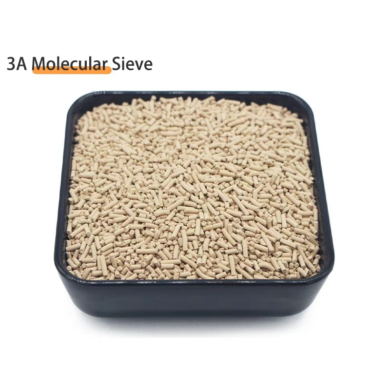
Molecular Sieve — 3A / 4A / 5A / 13X in Controlled Size Fractions
Supplied with per-lot particle size distribution by laser diffraction (ASTM D4365), bulk density, attrition index and bulk crush strength, so your pressure drop and capacity calculation is built on measured data rather than a nominal mesh.
View Product Details →Next Steps
If you are sizing a bed or comparing two size fractions, the fastest route to a defensible answer is to run the Ergun calculation with your own gas conditions and bed geometry, then compare it against the datasheet figure. Where the two differ by more than about 20 %, the difference is almost always one of the five unstated variables — void fraction, shape, size distribution, temperature or velocity — and it is worth resolving before the order is placed.
For buyers who want the calculation done against a specific charge, we can work through the size fraction, the bed mass and the blower duty for molecular sieve, activated alumina or a formed catalyst carrier, and return the Ergun calculation with its assumptions stated alongside the per-lot data for the delivered fraction. For a comparison across bulk media and granular grades, or for alumina powder used as a binder, send the application and the geometry and we will work through the test selection with you.
Talk to an engineer: WhatsApp +86 133 2522 2240 or email barry@aluminaworld.com. Share the application, the gas and its operating conditions, the flow rate and the bed geometry, and we will return a written size-fraction recommendation with the matching Ergun calculation and the specification clause — before the order is placed, not after.
💬 WhatsApp