Photovoltaic Polysilicon Production: TCSS Trichlorosilane Dryer with 3A Sieve and Iron Carryover Pitfalls
AluminaWorld is a Zibo, Shandong-based Chinese manufacturer (ISO 9001 certified) producing molecular sieves (3A, 4A, 5A, 13X), activated alumina (BET 300-360 m²/g), alumina powder, and aluminum hydroxide (ATH), with 15+ years of export experience serving 60+ countries. This article is written for process engineers and buyers who specify or maintain adsorbent in the trichlorosilane (TCS) drying train of a polysilicon plant.
The trichlorosilane (TCS) dryer in a polysilicon plant is a two-tower molecular sieve adsorption unit that removes water from the synthesis gas before it enters the fluidised-bed reactor, because water hydrolyses silicon tetrachloride back to silica and hydrochloric acid and destroys polysilicon yield. The standard adsorbent is a 3A molecular sieve (potassium exchanged LTA, 3 Å∠ aperture), chosen because its 3 Å sieve aperture admits water (kinetic diameter 2.65 Å) while excluding TCS (kinetic diameter ~4.0 Å) and the hydrogen chloride that accompanies it — so water is removed without stripping the product molecule from the feed.
That exclusion mechanism is exactly why the TCS dryer is the most mis-specified adsorbent application in polysilicon, and why it is also the one most sensitive to trace iron. This guide covers the four failure modes that actually stop a polysilicon line: wrong pore aperture, chloride-driven framework damage, iron-catalysed hydrolysis, and regeneration gas mistakes that destroy 3A binder.
Why Polysilicon Plants Dry Trichlorosilane at All
Trichlorosilane (HSiCl3, TCS, boiling point 31.8 °C) is the dominant feedstock for the Siemens process. In the reactor it reacts with hydrogen:
HSiCl3 + H2 → Si (solid) + 3 HCl
The failure mode nobody budgets for is the reverse reaction. Any water reaching the reactor hydrolyses the silicon-bearing species:
HSiCl3 + 3 H2O → SiO2 (solid) + 3 HCl + H2
Silicon dioxide precipitates as fine particulate inside the fluidised bed. It fouls the fluidising distributor plate, agglomerates the silicon particles, and drops the polysilicon deposition rate. Plants routinely report a 10–25% yield loss attributed to "reactor instability" that in fact traces back to water carried through from the drying tower. That is why the moisture spec on TCS feed gas is usually quoted at 0.01 vol% (100 ppmv) or tighter at the reactor inlet, with the drying tower itself specified far below that.
Why 3A Molecular Sieve and Not 4A, 5A, 13X, or Activated Alumina
Selecting a drying adsorbent is a molecular-size exclusion problem. The feed contains the species you want to keep (TCS, HCl, H2) and the species you want to remove (H2O). The pore aperture must pass water and reject the rest.
| Adsorbent | Effective aperture | Water uptake at 25 °C, 10% RH | TCS feed behaviour |
|---|---|---|---|
| 3A (K-LTA) | 3 Å | ~20–21 wt% | Correct choice — excludes TCS and HCl |
| 4A (Na-LTA) | 4.1 Å | ~21–22 wt% | Aperture too large — slow TCS diffusion into bed |
| 5A (Ca-exchanged) | 5 Å | ~19–20 wt% | Absorbs TCS — product loss, bed poisoning |
| 13X (Na-X) | 7.4 Å | ~20–21 wt% | Adsorbs HCl and H2S strongly; HCl poisons first |
| Activated alumina (300–360 m²/g) | Distribution, not discrete | ~18–20 wt% | Reactive surface — chlorination, HCl release |
The 3 Å aperture of 3A is smaller than the kinetic diameter of TCS, so TCS molecules cannot diffuse into the cage. Water is small enough (2.65 Å) to enter freely. 4A is close enough to work that plants get away with it for general purpose air drying, but at the 4.1 Å aperture the diffusion selectivity against TCS drops sharply and working capacity falls once the bed surface is partially loaded. 5A is categorically wrong here: it will take up your product.
Activated alumina deserves a specific warning. It is a reactive transition alumina, not a molecular sieve. Under anhydrous HCl at 30–60 °C, its surface converts to aluminium chloride, and the chloride-bearing surface then catalyses TCS hydrolysis in the presence of any residual moisture. It is not a substitute for 3A in this service, regardless of what a datasheet claims about "high HCl resistance."
Failure Mode 1: Chloride Attack on the Binder and Framework
TCS feed gas is never pure TCS. Commercial material carries 0.5–3 vol% HCl and trace higher chlorides, and the HCl content rises sharply if the upstream distillation column is operated with a high-boiling cut. Anhydrous HCl at elevated temperature does two things to a 3A bed:
- Binder degradation. Most 3A is extruded or beaded with an inorganic binder (clay or alumina). Chloride attack on the binder matrix, combined with thermal cycling, produces fines. Attrition index per ASTM D4058 rises, dust carries downstream, and the guard bed upstream of the reactor silts up.
- Cation exchange. HCl displaces K+ from LTA with H3O+. Potassium loss directly shrinks the 3 Å aperture, so the effective molecular diameter grows and the selectivity against TCS collapses. A degraded bed does not announce this — it slowly starts stripping TCS.
The practical signature is a slow drift: dew point stays nominally in spec for weeks while measured TCS pickup in the product gas rises. Ask your supplier for the binder chemistry, not just the aperture. A potassium-form LTA with an alumina-based binder tolerates this service better than a sodium-re exchanged variant, because it never had the wrong cation to lose in the first place.
| Bed condition | Dew point at exit | Attrition index (ASTM D4058) | Diagnosis |
|---|---|---|---|
| New charge | −60 to −70 °C | < 2.0 wt% | Baseline |
| ~6 months | −58 to −68 °C | 2–4 wt% | Normal chloride load, monitor trend |
| ~12–18 months | −50 to −60 °C | 4–7 wt% | Binder degradation; plan swap |
| Severe / HCl excursion | −40 °C or warmer | > 7 wt% | Framework damage; bed not recoverable |
Failure Mode 2: Iron Carryover — the Silent Hydrolysis Catalyst
This is the failure mode specific to polysilicon, and it is worth understanding because the mechanism is not intuitive. Water is the reactant that destroys yield, and the plant dries the gas to remove water. But iron in the system converts a passive system into an active one.
Iron exists in TCS as soluble chlorocomplexes, principally FeCl4−, at trace levels. Under the reducing, hydrogen-rich conditions upstream of the reactor, FeCl4− is reduced and deposits metallic iron on surfaces it contacts. Once metallic iron is present, it catalyses hydrolysis of the silicon chlorides dramatically:
Fe0 + 2 HSiCl3 + 3 H2O → SiO2 + FeCl2 + 2 HCl + H2
The consequence for adsorbent selection is specific and important: metal catalytic activity sits inside the pore system, not only on the surface. A 3A bed used as a guard or polish stage downstream of an iron-contaminated line will hold deposited iron in its cage structure. That iron keeps the hydrolysis channel open even after the bulk water has been removed, and it slowly releases iron back into the product gas. Standard corrosion and chloride specs on a CoA will not catch this, because the incoming iron is a process contaminant, not a property of the adsorbent.
Where does the iron come from? In descending order of observed frequency: carbon steel components used upstream of the dryer (a specification error — the whole TCS wet side should be 316L or equivalent); residual mill scale from fabricated pipe that was never pickled; and carryover from the silicon powder handling side in shared utility corridors. Specify the drying train in 316L or Hastelloy-class materials and specify the adsorbent loader in 316L, and you remove most of the iron source before the adsorbent ever sees it.
Failure Mode 3: Regeneration Gas Composition Errors
The 3A bed is regenerated in-situ with hot purge gas. Almost every early-life bed failure in this service traces back to the regeneration step rather than the adsorption step, and the same three mistakes recur.
Do not use TCS-bearing purge gas
Regeneration must use a gas stream free of both water and TCS. If a plant uses the product-side stream as purge, the heat releases water from the bed into a gas that still contains TCS, and the hydrolysis reaction runs backwards into the bed. The bed takes damage every cycle and nobody sees it because the dew point looks fine. Purge from a clean dry hydrogen or nitrogen header.
Respect the 350 °C ceiling on 3A
Standard 3A is specified for regeneration at 180–350 °C, with 350 °C being the practical maximum for standard binder grades. Above 350 °C, potassium-exchange LTA frameworks begin to degrade and the binder sinters, fusing beads into a monolith and destroying the pressure-drop profile. Some suppliers sell 3A as a high-temperature grade; if you are buying one, ask for the maximum stable regeneration temperature in writing and hold the operating setpoint at least 20 °C below it. Extruded 3A typically tolerates less thermal shock than beaded 3A, so never raise the regeneration temperature as a shortcut to a faster cycle.
Control the ramp rate, not just the setpoint
Thermal shock, not absolute temperature, is the common killer. Ramp the regeneration bed at no more than 3–5 °C/min and hold at temperature for 4–6 hours before switching back to adsorption. A fast ramp cracks beads internally; the fines show up two months later as a rising filter differential pressure, long after anyone connects the cause to the regeneration skid.
Failure Mode 4: Bed Sizing and Cycle Design Mistakes
Two adsorbent plants in the same polysilicon facility fail for the same reason: the second tower inherits the first tower's bed without a calculation behind it. The sizing inputs for this service are specific enough to state.
| Parameter | Industry-typical range | Design note |
|---|---|---|
| Inlet water content | 0.05–0.5 vol% | Measured at the dryer inlet, not assumed from the column |
| Exit water target | < 10–50 ppmv | Drives breakthrough timing, not just bed size |
| Working capacity (3A, actual) | 8–12 wt% | Never use the 20–21 wt% static figure for design |
| Adsorption cycle | 6–10 h | Two towers, one in adsorption one in regeneration |
| Regeneration temp | 300–350 °C | Standard binder grade ceiling |
| Ramp rate limit | 3–5 °C/min | Prevents internal bead cracking |
| Service life | 12–24 months | Shorter with high HCl or iron carryover |
The single most common sizing error is using the static water uptake figure. A 3A charge that looks like it holds 20 wt% of water will deliver 8–12 wt% in a dynamic cycle at 300 —350 °C regeneration, because mass-transfer zone length and incomplete regeneration both eat capacity. Size on the dynamic number with a 20% design margin on top.
Procurement Specification: What to Actually Write in the RFQ
Most RFQs for this application specify particle size and nominal water uptake and stop there. Those two parameters are necessary and nowhere near sufficient. The specification that reliably produces a bed that survives a year in TCS service needs the following.
- Aperture and cation form: 3A, potassium form LTA, with written confirmation that no sodium-exchange step has been applied. Specify the potassium content range; typical industrial 3A runs 18–21 wt% K2O equivalent.
- Binder chemistry: alumina-based binder preferred over clay for chloride service. Ask for the binder formulation category, not the exact recipe.
- Attrition index per ASTM D4058: require a numeric value, not "conforms". Industrial 3A typically reports < 2.0 wt%. Hold the supplier to it in the contract.
- Maximum stable regeneration temperature, in writing. This is the number that prevents the 350 °C overrun.
- Crush strength and particle size distribution: 3 × 1 mm beads or 2.5 mm extrudate are normal for this service. Request the full distribution curve and a fines percentage.
- Iron content limit on incoming material. Specify a maximum, typically < 200 ppmw Fe2O3 on the finished product. This costs nothing if the supplier uses alumina feedstock, and it is a meaningful control if they do not.
- APPE appearance and retained capacity after 200 cycles of simulated water loading, reported on the CoA. This is the closest proxy to service life you can obtain without a pilot.
On delivery inspection, sample per ASTM E300 chain-of-custody practice and check three things before the charge goes in the tower: particle size distribution by sieve analysis, crush strength on a sample of 20 beads, and an ICP check on the lot for iron and calcium. Iron and calcium are the two that matter here, and neither appears on a typical commercial CoA.
Operating Discipline: The Four Checks That Predict Bed Failure
Once the bed is installed, a short monthly routine catches a deteriorating charge long before the reactor does. All four checks take under an hour and require only instruments the plant already has.
- Trend exit dew point on both towers, every cycle. The absolute value matters less than the trend. A tower whose exit dew point drifts 10 °C warmer over six months while feed conditions are unchanged is telling you the bed capacity is falling.
- Measure TCS pickup, not just water removal. Take a grab sample of the product gas and analyse for TCS content. Rising TCS in the dried product means the 3A has lost effective selectivity — the most direct early indicator of cation loss from chloride attack.
- Watch inlet guard filter differential pressure weekly. Rising DP means fines are being generated in the charge. This is the earliest mechanical evidence of binder breakdown, and it appears 4–8 weeks before the dew point moves.
- Sample the reactor feed for iron quarterly. If iron is climbing, the source is upstream materials or the adsorbent itself. Do not treat this as a dryer problem to be solved by changing adsorbent.
Related Adsorbent Options for Adjacent Polysilicon Services
Two other positions in the same plant use different adsorbents, and specifying 3A there is a common and expensive mistake. On the high-temperature HCl off-gas from the reactor, the contaminant is acid gas rather than water, so the material must tolerate a strongly acidic, wet stream — a different problem entirely. For the general picture on molecular sieve grades and their pore apertures, and for the activated alumina product line including the reactive-surface grades used in acid service, see the product pages. Our electronic-grade specialty gas drying guide covers ppb-level drying for NF3 and SiH4, which is the same exclusion principle taken to its limit, and 4A molecular sieve for ethylene and ETO drying covers the chlorinated-hydrocarbon drying case where 4A does work because the larger molecule is still excluded by pore geometry.
For the general selection logic behind 3A versus 4A, and how cation exchange governs which water you remove, our 3A molecular sieve application guide and cation modification and water vapour adsorption on alumina desiccants cover the underlying chemistry in more depth. If your team needs to compare 3A against alternatives for a new line, activated alumina versus molecular sieve in compressed air drying gives the side-by-side capacity and regeneration cost comparison that usually settles the argument internally.
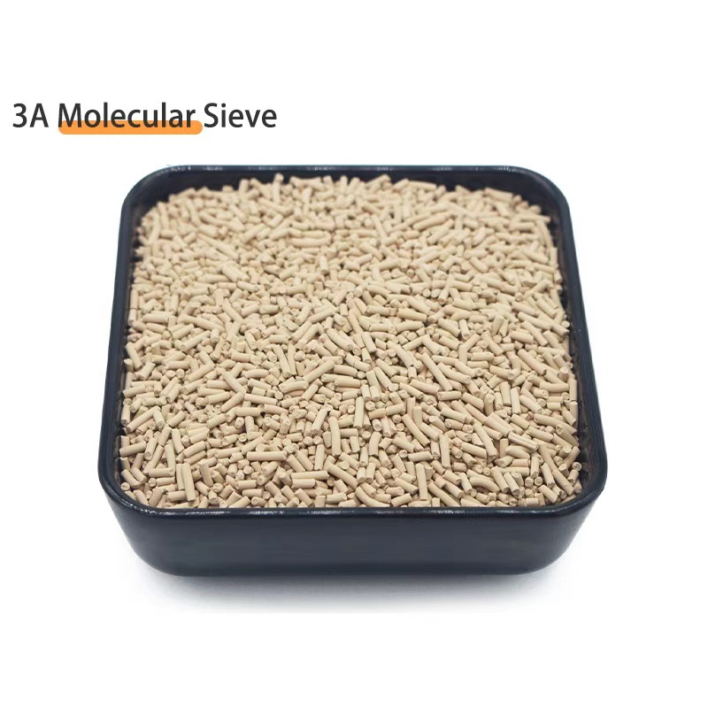
3A Molecular Sieve (Potassium LTA, 3 Å)
Binder-controlled attrition and documented chloride tolerance for TCS, ETO, and other chlorinated-silane drying duties. COA and MSDS on every lot, sample available before volume order.
View Product Details →Next Steps
If you are specifying a new TCS dryer, send us the inlet water content, the HCl level, your regeneration gas source, and the bed volume you have available. We will return a 3A grade recommendation with the dynamic working capacity we expect at your actual cycle conditions, plus the binder and iron limits we would put in the contract. For an existing bed showing drift, send a used-media sample with the ASTM E300 chain-of-custody paperwork and we will run retained-capacity and ICP analysis on it before you commit to a replacement order.
Frequently Asked Questions
Why does polysilicon production dry trichlorosilane before the reactor?
Because any water reaching the reactor hydrolyses the silicon chlorides back to silica and hydrochloric acid. Hydrolysis generates fine SiO2 particulate inside the fluidised bed, which fouls the distributor plate and agglomerates the polysilicon particles. Plants typically lose 10–25% of theoretical yield to instability that traces back to moisture carryover, which is why the reactor inlet spec is usually 0.01 vol% water or tighter.
Why is 3A the standard adsorbent for TCS drying rather than 4A?
Because 3A has a 3 Å aperture, smaller than the kinetic diameter of TCS, so the product molecule cannot diffuse into the cage while water at 2.65 Å enters freely. 4A at 4.1 Å still excludes TCS in principle, but the selectivity margin is narrow enough that working capacity falls once the bed surface is partially loaded. 5A and 13X will absorb TCS or HCl and cause product loss.
Can activated alumina be used as the TCS dryer adsorbent?
Not as a substitute. Activated alumina is a reactive transition alumina, not a molecular sieve. Under anhydrous HCl at 30–60 °C its surface converts to aluminium chloride, and the resulting chloride-bearing surface catalyses TCS hydrolysis rather than preventing it. Use 3A for this service.
How much iron is too much in a 3A charge for TCS duty?
Specify a maximum Fe2O3 content on the finished product, typically below 200 ppmw, and require an ICP result on the CoA because commercial CoAs rarely include it. Metallic iron deposited in the pore structure catalyses hydrolysis of the silicon chlorides, which sustains silica generation even after bulk water has been removed. The better control is upstream materials: specify 316L or Hastelloy for the entire TCS wet side including the adsorbent loader.
What is the maximum safe regeneration temperature for 3A molecular sieve?
Standard binder-grade 3A is rated for 180–350 °C, with 350 °C as the practical ceiling. Above that, potassium-exchange LTA frameworks degrade and the binder sinters, fusing beads into a monolith and destroying the pressure-drop profile. Hold your setpoint at least 20 °C below the supplier's documented maximum and never raise temperature to shorten cycle time.
How fast can the regeneration bed be ramped?
No more than 3–5 °C/min, with a 4–6 hour hold at temperature before switching back to adsorption. Thermal shock, rather than absolute temperature, is what cracks beads internally. The fines appear as a rising filter differential pressure two months later, well after anyone connects the cause to the regeneration skid.
What regeneration gas should be used for a TCS dryer?
A clean, dry hydrogen or nitrogen header free of both water and TCS. Using the product stream as purge gas releases the bed's water into a gas that still contains TCS, driving hydrolysis backwards into the charge on every cycle. The damage is progressive and invisible, because exit dew point continues to look acceptable.
What dynamic working capacity should I use for 3A bed sizing?
8–12 wt% in service, not the 20–21 wt% static figure. Mass transfer zone length and incomplete regeneration both consume capacity, and the gap between static and dynamic numbers is exactly where undersized beds come from. Apply a further 20% design margin on top of the dynamic figure.
How can I tell that a 3A bed is suffering chloride attack?
Three signals, in order of appearance: rising differential pressure on the inlet guard filter as fines generate, a slow upward drift in exit dew point that feed conditions do not explain, and measurable TCS in the dried product gas. The third is the most direct indicator, because it means potassium has been exchanged out of the LTA and the aperture has effectively widened.
How long does a 3A charge last in polysilicon TCS service?
Industry-typical service life is 12–24 months at typical chloride load. High HCl in the feed or iron carryover from upstream materials shortens that materially. Rather than scheduling replacement on a fixed calendar, trend exit dew point, guard filter DP, and product TCS content monthly; those three together give a reliable remaining-life estimate.
Which ASTM standards should I write into the adsorbent purchase specification?
ASTM D4058 for attrition index (require a numeric value, ideally below 2.0 wt% for 3A beads), ASTM E300 for sampling and chain-of-custody, and a sieve analysis for particle size distribution. Add a crush-strength check on a sample of 20 beads as an incoming inspection item. Also require the maximum stable regeneration temperature in writing, because that number is not usually printed on a datasheet.
Is binder type a real selection criterion, or is it a detail?
It is a real criterion in chloride service. Most 3A is extruded or beaded with an inorganic binder, and chloride attack combined with thermal cycling degrades it. An alumina-based binder tolerates this service better than a clay binder. Most importantly, request the potassium content range as well: a properly potassium-exchanged LTA has no wrong cation left to lose, whereas a sodium-re variant can degrade even when the aperture looks correct.
What water content should the dryer exit target for the reactor inlet?
Typically below 10–50 ppmv at the dryer exit, which gives margin to the 0.01 vol% reactor inlet spec after line and heat-exchanger pick-up. Measure inlet water content rather than assuming it from the upstream distillation column, because column upset is the most common single cause of a sudden breakthrough.
How do I prove the delivered lot is fit for TCS service before charging the tower?
Sample under ASTM E300 chain-of-custody, then run four checks: sieve analysis for particle size distribution including fines percentage, crush strength on 20 beads, retained water capacity after a simulated 200-cycle loading protocol, and an ICP screen for iron and calcium. Iron and calcium are the two parameters that matter most here and neither appears on a typical commercial CoA. A lot that fails the ICP screen should be rejected even if the water uptake figure is excellent.