Adsorbent Static Bed Height vs Dynamic Working Capacity: How Compression Set Quietly Costs You 8-15% of a Working Bed
Primary reader: process engineer sizing or operating a PSA, TSA or fixed-bed adsorption vessel who has been handed a charge mass, a vessel height and a vendor capacity number, and has to work out whether the bed will still be doing the same job three years after it was charged. Almost every adsorbent datasheet quotes a capacity in weight percent, measured on a small sample in a laboratory column under a clean, dry, slow-flowing condition. That number is useful, and it is also the beginning of a chain of deductions that ends in a working bed. Between the datasheet and the plant sit four corrections: working capacity is lower than saturation capacity, lower again if the feed is wetter than the test condition, the bed settles under load, and it settles differently depending on whether it was charged as beads, pellets or extrudates. This guide works through the settlement step, because it is the one almost never in the purchase specification and almost always in the operating history.
Compression set is invisible at commissioning. The vessel is filled to the calculated height, the plant makes product to specification, and nothing appears wrong. Then over months to years the bed compacts, the void fraction falls, the mass transfer zone widens and working capacity falls with it. The symptom that reaches the operator is rarely "the bed settled"; it is "the regeneration cycle is getting longer" or "the product dew point drifted". Those get attributed to the adsorbent, the feed or the control system. Sometimes it is none of those: the bed was loaded 200 mm deeper than needed, and after 18 months of thermal cycling it has settled 25 mm and lost a tenth of its working capacity.
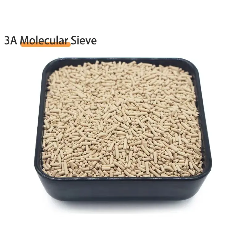
Static Bed Height Is a Measurement, Not a Design Input
The phrase "static bed height" is used loosely in the industry, and it helps to separate three numbers that get collapsed into one. The design bed height (charged or settled height) is the depth of adsorbent between the distributor and the top retention system, measured once, immediately after charging, before the plant has run. The in-service bed height is the same dimension measured during a shutdown, after an unknown number of cycles. The dynamic bed height is not a physical dimension but describes the bed in its working state.
The distinction matters because the mass of adsorbent is fixed once charged, but the volume that mass occupies is not. If the same mass packs into a smaller height because particles rearranged under load, the void fraction has dropped, the interstitial volume for gas has fallen, and every molecule passing through sees a more restricted flow path. Nothing was added or removed; capacity changed because the geometry changed.
A second-order effect matters more than most people expect: the top and the bottom of the bed do not experience the same load. The bottom carries the weight of everything above it plus the gas pressure differential, typically 0.3 to 1.5 bar in a downflow adsorber. The top carries only its own weight, about 7.5 kPa of overburden for a 1,200 mm bed of 640 kg/m3 material. The stress difference is enormous, so compaction is strongly graded: dense at the bottom, loose at the top.
This is also why compaction is hardest to diagnose in the vessels where it costs most. In a large PSA bed with 1.5 to 4 m of charge, the bottom third can sit at a void fraction materially below the design value while the top third is above it. A single sample from the top, which is what most operators can reach without a full unload, reports a bulk density that looks entirely normal.
Three Capacities: Equilibrium, Kinetic and Dynamic
The term "capacity" covers at least three quantities in adsorption engineering, and the confusion between them accounts for a large share of the gap between what a buyer expects and what a plant delivers. The framework is classical and appears in Breck's standard reference on zeolite molecular sieves: the three are commonly labelled P (working), X (equilibrium) and Y (kinetic) capacity.
- X, the equilibrium capacity, is the amount of adsorbate the material holds when the solid and the gas phase are in thermodynamic equilibrium at a given loading and temperature. This is the number a datasheet quotes when it says 4A molecular sieve has 18 to 21 wt% water capacity. It is measured by exposing a known mass of adsorbent to a known gas composition at a known temperature, then measuring the uptake at saturation.
- Y, the kinetic capacity, is the amount adsorbed before the material has reached equilibrium at the particle scale. This is the difference that makes a large bead and a small bead different products even when they have the same X: a 2.5 mm bead needs roughly four times longer to equilibrate than a 1.6 mm bead under the same conditions, because the diffusion path scales with the square of the radius.
- P, the working (dynamic) capacity, is what the process actually recovers between regenerations under real cycle conditions: real feed composition, real flow rate, real switching times, real temperature. P is always less than Y, and Y is always less than X.
The ratio between them is not a fixed property of the adsorbent; it is a property of the adsorbent in a specific vessel under a specific cycle. Typical working swings for a two-bed PSA cycle at 60-80% relative humidity feed with 4A or 5A are 8 to 11 wt% of the charge mass, against an equilibrium capacity of 18 to 21 wt%. The process typically recovers 45 to 55% of saturation capacity; the rest is lost to incomplete saturation, to water hold-up in the void gas at the end of regeneration, and to breakthrough being a gradual curve.
| Capacity | What it measures | How it is measured | Typical 4A/5A value at 20 °C | Who uses it |
|---|---|---|---|---|
| X (equilibrium) | Total uptake at thermodynamic equilibrium | Saturated weighed sample, desorption at controlled temperature | 18-21 wt% H2O | Grade comparison, CoA specification |
| Y (kinetic) | Uptake before particle-scale equilibrium | Fixed-time exposure then immediate desorption | 14-18 wt% at 30-60 min | Cycle-time selection, mass transfer zone width |
| P (working) | Net recovered between regenerations | Continuous breakthrough curve, real feed and cycle | 8-11 wt% in a 2-bed PSA | Vessel sizing, media charge mass, TCO |
Every one of these numbers is conditional on the bed's packing geometry, and that is where compaction enters. The Y value is not a property of the pellet but of the pellet in a bed with a given void fraction and velocity distribution. When the bed compacts the interstitial flow area shrinks, the residence time distribution broadens at the low-velocity tail and effective Y drops. Working capacity P drops with it, as a lengthening of the mass transfer zone rather than any change a CoA would reveal.
What Compression Set Actually Is, Mechanically
Compression set, in the adsorbent context, is the permanent reduction in bulk volume of a bed under sustained mechanical load. It is not attrition, which is the generation of fines, and not crushing, which is fracture of individual particles. It is a bulk rearrangement: the particles are largely intact, but their packing has densified, because the load has let particles slip past one another, reorient, and settle into a lower-void configuration.
Three mechanisms drive it, and they operate at different rates:
- Initial seating. Immediately after charging, the bed is loose. Vibration from vessel filling, from the impact of the loading chute, and from the first few pressure swings allows particles to rearrange. A 1 to 3% height reduction in the first days is normal and is not a defect. This is why bed height is specified after settling, not before.
- Thermal cycling settlement. Each regeneration heats the bed from ambient to 180-350 °C and cools it back, and the adsorbent has a thermal expansion coefficient roughly an order of magnitude higher than the steel vessel. Repeated cycles drive an irreversible sintering-like rearrangement of the packing, particularly at particle contacts where the forming binder is present as a small amount of glassy phase. This is the dominant long-term mechanism and it is tied to the number of cycles, not to elapsed time.
- Overburden creep. The static weight of the bed above a given layer, plus the pressure differential, produces a slow creep of the packing. For a 4 m charge this can be several hundred kPa at the bottom. Creep is slow, monotonic and irreversible, and it produces the slow decline operators observe over a multi-year campaign.
The important mechanical consequence is that compaction does not stop at a new equilibrium. It asymptotes, but slowly, and the asymptote is above the ideal packing density. A bed charged to design height is therefore still settling after commissioning. If the vessel has no headroom, the bed eventually settles into the top distributor or retention grid.
Measuring the Compaction: Void Fraction, Bulk Density and the Bed Height Survey
Compaction is measurable, but not with the instruments most people reach for first. A single bulk density sample gives the average state of the bed, not the distribution. Three measurements characterise a settled bed: a bulk density measurement by a recognised method, a void fraction calculation from that density and the apparent particle density, and a height survey up the vessel wall.
Bulk density for a granular adsorbent is normally determined by a standardised method specifying both compaction procedure and container volume, because the result depends on how hard the sample is tapped. A reproducible purchase specification must name the method, compaction level and sample conditioning: a factor-of-three difference in tapping energy can move reported bulk density by 4 to 6% on a 4A bead charge, the same order as the compaction effect itself.
The void fraction then follows from the two densities:
ε = 1 − (ρbulk / ρparticle)
With an apparent particle density for a 4A bead of 1.25 to 1.35 g/cm3 (typical for a synthetic zeolite bead of that grade) and a fresh-bed bulk density around 0.64 g/cm3, the void fraction works out to roughly 0.49 to 0.51. For a 13X pellet at an apparent density near 1.30 g/cm3 and a bulk density near 0.63 g/cm3, it is around 0.52. After a bed settles 4% in height under load, the void fraction falls by roughly 4 percentage points, close to 8% of the original void volume. That is the number that matters, because interstitial volume is what the gas moves through.
| Bed state | Bulk density (g/cm3) | Void fraction ε | Height for 1.0 m charge | Relative working capacity |
|---|---|---|---|---|
| Fresh charge, immediately after filling | 0.615 | 0.53 | 1,000 mm | 100% (reference) |
| After first seating, 5 cycles | 0.632 | 0.51 | 973 mm | 98-99% |
| After 500 cycles, thermal cycling only | 0.658 | 0.48 | 934 mm | 93-95% |
| After 2,000 cycles + overburden creep | 0.688 | 0.45 | 893 mm | 87-91% |
| Compacted zone at the bed bottom, loaded | 0.720 | 0.42 | 857 mm | 85-88% (local) |
These figures are a design allowance rather than a specification, because they depend strongly on the product, the load history and the vessel geometry. They are an order-of-magnitude frame, labelled as typical industry behaviour rather than a property of any specific grade.
The bed height survey catches what the bulk density sample misses. It is done during a planned shutdown, with the vessel depressurised and at ambient temperature, measuring from a fixed reference datum to the top of the bed at a series of elevations with a graduated rod or laser distance meter. Readings at the bottom, middle and top give the settlement profile, which tells you whether the bed settles uniformly (thermal cycling) or preferentially (load, a support grid problem or a distributor problem).
Why the Loss Lands in the 8-15% Band
The headline figure is the number a plant engineer sizes against. The chain is short, and each link is individually verifiable.
Link 1: volume loss. A bed that settles 4 to 7% in height loses 4 to 7% of its bulk volume. Since the mass is unchanged, bulk density rises by the same proportion and the void fraction falls by 2 to 4 percentage points. Interstitial volume, which was 48 to 52% of the bed, is now 44 to 48%.
Link 2: reduced effective void. Void fraction is not uniform inside a settled bed even before loading. The wall region is naturally less dense than the core because the wall prevents radial rearrangement, and the settled profile compounds that. A bed with a bulk void fraction of 0.47 is probably running at an effective interstitial void near 0.40 in the core and 0.52 at the wall.
Link 3: mass transfer zone widening. The height of the mass transfer zone for a given breakthrough criterion depends on the ratio of the mass transfer coefficient to interstitial velocity. Halving interstitial velocity through a compacted core stretches the transfer zone. A zone grown from 8% of bed height to 11% is worth roughly 3% of working capacity on its own, because the last part of the bed no longer contributes at design purity.
Link 4: increased pressure drop. The Ergun inertial term scales with particle diameter squared and velocity squared, so the same mass flow through a 4% smaller void fraction at the same superficial velocity raises pressure drop noticeably. The plant responds by either reducing flow, which extends cycle time, or raising pressure, which changes the adsorption equilibrium and reduces the working swing. Both cost capacity or energy.
Link 5: the settled bed is not the designed bed. If the vessel was charged to design height rather than design mass, the charge mass is unchanged but the available gas volume is smaller, so specific throughput has gone up. If charged to design mass, the bed has settled into the distributor clearance, pushing the top of the bed into the retention grid and concentrating the pressure drop where the gas enters.
Adding these effects produces the observed band. The 8 to 15% loss of working capacity from compression set is the range that shows up repeatedly in operating plant over multi-year campaigns, and the high end applies where the charge is deep, the regeneration temperature is high, the adsorbent is a pellet rather than a bead and the overburden is significant.
Form Factor Changes the Compaction Rate, Not Just the Amount
The other half of the question is which product form you are compacting, because a bed of 4A beads and a bed of 5A pellets behave differently under the same load even at the same nominal diameter. The reason is that a formed pellet has a different internal structure, binder content and contact geometry than an extruded-and-rounded bead.
| Form factor | Typical diameter | Crush strength (ASTM D4058 attrition index) | Compaction tendency | Dominant consideration |
|---|---|---|---|---|
| Rounded bead, binderless | 1.6-2.5 mm | Low attrition index (better) | Lowest; spherical particles roll and rearrange freely | Kinetic capacity, long cycle times |
| Extrudate, rounded ends | 1.6-3.0 mm | Moderate | Moderate; contact area reduces rearrangement | Balance of capacity and crush strength |
| Triclobe / tablet | 1.6-3.0 mm | High crush strength | Low; flat faces lock the packing | Erosion resistance in high-velocity service |
| Tabletular alumina | 4-6 mm | Very high | Very low | Catalyst support, not primary adsorption |
Note what the table does and does not say. Crush strength and compaction tendency are correlated but are not the same variable, and the correlation is not a guarantee. High crush strength prevents particle fracture; it does not prevent the packing from densifying. A triclobe still settles, it simply locks into configuration earlier and stops. A rounded bead settles more, but generates fines that fill the interstices and stabilise the packing at a lower void fraction. In both cases the end state is a denser bed than the fresh charge, reached by a different path.
The specification implication is that "bed height" cannot be specified independently of form factor, and that a charge specification listing only a mesh size and a bulk density is not reproducible. It needs the form factor named, the compaction method for the bulk density named, and either a settled-height tolerance or a compaction-set test.
Designing for Settlement: Headroom, Distributor Clearance and the Charged-Mass Method
There are two ways to specify how much adsorbent goes into a vessel, and they give different answers under settlement.
The charged-height method specifies bed depth after settling, typically a range such as 1,000 to 1,050 mm. The installer fills the vessel and settles the bed, adding material until the settled height is in range. This directly controls the void fraction, which is what the design calculation assumed. Its weakness is that it does not control the mass of adsorbent, and therefore not directly the capacity, so two vessels built to the same height can carry meaningfully different loads if bulk densities differ.
The charged-mass method specifies the mass of adsorbent, computed from design capacity and working capacity, and lets the height follow. This directly controls capacity, which is what the purchase contract is about, and is the method a disciplined engineer uses. Its weakness is that the resulting height depends on the lot's bulk density, so the settlement allowance must be added on top, and the bed must still clear the retention system at end of life.
The correct practice is to use the mass method for capacity and apply an explicit settlement allowance to the geometry. A reasonable allowance for a bed seeing several thousand thermal cycles is to design for a final settled height of charge height plus 3 to 5%, and check distributor clearance against that final height rather than the fresh charge. On a 2,000 mm bed that is 60 to 100 mm, not trivial when the vessel is 90% full at the vendor's minimum order of one metric ton.
Two further details repay attention. The top distributor and retention grid should be sized so gas entry area is not the constraint once the bed has settled, because a bed that has crept up against a small-area top screen will channel, and that channeling will be mistaken for a capacity problem. And where overburden matters, the vessel support should be specified for the worst case, sized for the fully compacted density rather than the fresh bulk density.
Diagnosing a Bed That Has Lost Capacity
When a bed's performance declines, the compaction hypothesis is one of several, and it must be distinguished from adsorption-site contamination, water carryover from the upstream compressor, an eroded or blinded distributor, and a drifted instrument. The sequence below separates them, cheapest and least invasive checks first.
- Check the trend, not the point. Pull the bed temperature profile, the cycle timing history and the product purity history for the last 24 months. Compaction is monotonic. Contamination from a compressor upset is a step change. An instrument drift is a step change in one variable only. A steady deterioration in cycle length with product purity still in specification is the classic compaction signature.
- Check the pressure drop trend. A compacted bed shows a rising pressure drop across the vessel at the same flow rate. A poisoned bed shows rising pressure drop with an unchanged or improving product purity. A blinded distributor shows a step change in pressure drop with a step change in product purity.
- Confirm with a settled-height survey. During the next shutdown, measure the bed height at the bottom, middle and top. This is the decisive measurement, because it measures the cause rather than the symptom.
- Sample the bed in sections. A sectioned sample from top to bottom, following the approach set out in the field sampling guidance for spent adsorbent beds, gives the density profile and the contaminant profile at the same time. A single composite sample destroys the diagnostic value, because it averages away exactly the gradient you are trying to detect.
- Cross-check the bulk density against the certificate. Compare the measured in-service bulk density with the certified value on the same grade. A 5% rise is consistent with normal compaction. A 20% rise suggests localised over-compaction, a wet-dry cycling problem, or contamination with fines from a different source.
If the survey confirms settlement, the recovery options are not equally attractive. Regrading is cheap when the vessel is open, but it only redistributes the problem since regraded material recompacts, and needs a fresh bulk density measurement to re-establish the design basis. Changeout is the clean answer and restores the original working capacity, but is a capital and downtime decision. Topping the bed up to restore design height is what most plants reach for first and the option most likely to make things worse: it does not restore the void fraction in the compacted zone.
Writing the Specification So This Argument Never Happens
Five clauses, each aimed at a specific failure mode, make the compaction behaviour of a charge verifiable at three separate points: incoming inspection, commissioning, and any claim made three years later.
Clause 1 — form factor and dimensions. Name the form (bead, extrudate, triclobe, tablet), the nominal diameter, the particle size distribution method and the fines limit. ASTM D4365 (laser diffraction) and sieve analysis both appear in practice, and the method must be named because a laser diffraction result and a sieve result on the same material are not the same number. State the maximum fines fraction: fines in the incoming charge seed the accelerated compaction case.
Clause 2 — bulk density with a named method. Specify the method, the container volume, the compaction procedure and the conditioning. State the value as a range with a method attached, not as a single number, and require the certificate to report the same method so that a receiving inspection can reproduce it.
Clause 3 — apparent particle density and the derived void fraction. The void fraction is the design variable. Ask for the apparent density and state the target void fraction, or state the target void fraction and let the supplier demonstrate that the certified bulk density and apparent density pair produces it. It is a short clause, and the one that protects the design calculation.
Clause 4 — settled bed height tolerance and the settlement allowance. State the design settled height, the tolerance on the installed settled height, and explicitly the vessel geometry requirement that the bed retain clearance from the top distributor after the full cycle count in the design basis has been applied. This converts an unquantified risk into a specified allowance.
Clause 5 — cycle-life definition and the settlement test. Define cycle life by the number of regeneration cycles, the regeneration temperature and the pressure swing, and specify a settlement or compaction-set test method where one exists for the form factor. Where the supplier has no standard method, a defensible alternative is a post-cycling settled-height limit on a sample held under a defined load at a defined temperature for a defined number of cycles, as a percentage of initial height.
And add the clause that matters commercially: a change of form factor or binder during the supply agreement is a specification change requiring re-approval. A grade "equivalent" on water capacity and particle size but different in form factor has a different compaction rate, and the plant was designed around the original one.
Frequently Asked Questions
Does an adsorbent bed really lose 8-15% of its working capacity from compression set, or is that an extreme figure?
It is a range, not a constant: working capacity relative to the freshly-charged bed over a multi-year campaign with several thousand regeneration cycles. The low end applies to shallow beds of robust form factor at modest regeneration temperature; the high end to deep beds of extruded or pellet form at high temperature with significant overburden. This is a loss against the fresh charge, not the datasheet working capacity.
How many regeneration cycles does it take before compaction becomes measurable?
Initial seating settles within the first few cycles and is normally complete within commissioning. Measurable divergence from the fresh-charge density typically appears after several hundred cycles, the rate slowing as cycle count rises. A practical monitoring rule is to take a baseline settled-height and bulk-density reading after the first 50 to 100 cycles and compare annually against it, rather than detecting compaction against a theoretical value never measured in your vessel.
Can the loss be avoided by choosing a higher-crush-strength product?
No, and this is a persistent misconception in specification reviews. Crush strength resists particle fracture and therefore resists attrition and fines generation. Compression set is a bulk rearrangement of intact particles, and a harder pellet in the same size fraction settles into a denser packing at least as readily as a softer bead. Specify crush strength for attrition resistance and void fraction for compaction control; they are separate clauses.
How do I measure the void fraction of a bed that is already in service?
You need the in-service bulk density and the apparent particle density of the grade, with bulk density measured by a specified method rather than an improvised one. In-service bulk density comes from sectioned sampling at known elevations, or a mass balance if both the charge mass and bed volume are known. A single sample from the top is not representative, because the bed does not compact uniformly. Bottom-of-bed density matters most, where overburden is greatest.
Does bed compaction affect activated alumina the same way it affects molecular sieve?
The mechanism is the same and the numbers similar in form, but the magnitudes differ. Activated alumina is a porous formed material with an apparent density of 0.80 to 0.95 g/cm 3 and a bulk density of 0.35 to 0.50 g/cm 3 , so overburden for a given bed height is lower and the creep component of settlement correspondingly smaller. Molecular sieve beads and pellets carry higher bulk density and therefore higher overburden. The thermal cycling component is broadly similar, though the higher regeneration temperature typical of molecular sieve service (180-350 °C) drives a more aggressive rearrangement than the 180-250 °C common in activated alumina duty.
Is it acceptable to top up the bed with fresh adsorbent when it settles?
Generally no, and it is worth stating clearly because it is a common and expensive reflex. Topping up restores the height but not the void fraction in the compacted zone below; the new material sits on a bed with a restricted, uneven flow path, sees a different flow distribution from the one the vessel was designed for, and develops its own channeling. If the bed has compacted, the answer is regrade or changeout.
What does the pressure drop across the bed tell me about compaction?
It is a useful proxy with two caveats. A rising pressure drop at constant flow and temperature is consistent with a falling void fraction, but also with fines accumulation, a blinded or eroded distributor, or a fouled upstream filter. And because compaction is graded across the bed, the overall pressure drop is a weighted average that understates the change at the bottom. A multi-point pressure profile distinguishes graded settlement from a distributor problem far better than a single measurement.
Does the specification need to state a cycle life if the plant only runs seasonally?
Yes, and it should be stated in cycles rather than years, because compaction is driven by cycle count. A seasonal plant running 150 cycles a year for five years accumulates 750 cycles, while a continuous plant runs about 8,000 a year and reaches the same count in ten weeks. Stating life in years lets a supplier quote a grade adequate for the elapsed time while being wrong for the duty. Cycle count also determines the settlement allowance the vessel needs, so it belongs in the design basis as well as the purchase specification.
How much extra vessel height should I allow for settlement in a new design?
A commonly used engineering allowance is 3 to 5% of the design bed height for a deep bed with several thousand expected cycles, applied to the final settled height and checked against distributor clearance at the end of that cycle count. It is not universal, and should be derived from the supplier's own settlement data for the grade and form factor where that exists. The allowance must be applied to the settled height: a distributor sitting exactly at charge height on the day of filling will be contacted by the bed within two years.
Does compaction change the working capacity or only the kinetics?
Both, and the two have different remedies. The kinetics are affected directly: a reduced void fraction lowers interstitial velocity, which widens the mass transfer zone and lowers effective kinetic capacity. The equilibrium capacity of the individual particle is unaffected, because the crystal structure and pore system have not changed. The working capacity loss is therefore a bed-geometry effect, not a material effect, which is why recharging with the same grade restores performance and grading the existing material will not.
Does the choice of vessel orientation or charge method change the compaction rate?
The charge method matters more than most specifications acknowledge. A pneumatic or vacuum conveying charge arrives with a different size distribution and packing state than a gravity or chute charge, and can be more uniform but also more heavily attrition-damaged. Vertical vessels, the normal configuration for a deep bed, concentrate overburden at the bottom and produce the graded settlement profile described earlier. A wider, shallower bed of the same mass has lower overburden and settles less, a legitimate argument for a wider vessel where diameter is not constrained.
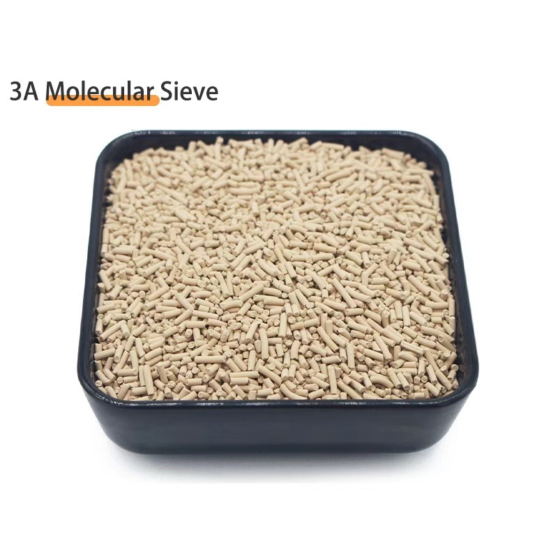
Molecular Sieve — 3A / 4A / 5A / 13X with Certified Bulk Density and Void Fraction
Supplied with per-lot particle size distribution, bulk density by a named method, apparent particle density and the derived void fraction, plus attrition index and bulk crush strength — so your bed geometry and settlement allowance can be calculated from data rather than assumed.
View Product Details →Next Steps
If you are sizing a bed, the fastest route to a defensible answer is to take the design working capacity, apply the X-to-P ratio for your actual cycle, apply a void fraction from certified data rather than a generic assumption, then check vessel geometry against the settled height after the full expected cycle count.
For buyers who want the calculation run against a specific charge, we can work through the bulk density, void fraction, design bed height and settlement allowance for your vessel geometry. See also our guides on pellet diameter vs bed pressure drop, PSA bed depth sizing and TCO, crush strength vs attrition index and sectioned sampling of a spent bed.
Talk to an engineer: Message us on WhatsApp or email barry@aluminaworld.com with your vessel geometry and cycle data, and we will return a settled-height allowance and a void fraction budget with the quote.